REQUIREMENTS/SPECIFICATIONS
Page 2-7
2.2.3 Ring Sequence
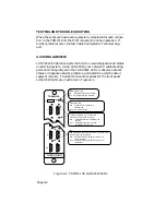
The ring sequence on the TRMIM-10R begins at the Ring-In, goes out
to the Flexible Network Bus (FNB) then, after threading through
other attached token ring boards, returns from the FNB to sequence
through the TCU ports (in port number order) and finally out the
Ring-Out port. The following example serves to illustrate the ring
sequence in an MMAC with multiple token ring boards:
Example: TRMIM-22P in slot 1 with ports 2, 5, 8, & 12 in use.
TRMIM-10R in slot 2 with ports 1, 2, 3, 5, and 6 in use.
TRMIM-12 in slot 3 with ports 1, 5, 7, 11, & 12 in use.
All three boards are attached via the FNB.
The ring sequence in this example is from Slot 2, Ring-In port via the
FNB to Slot 3, ports 1, 5, 7, 11, 12, via the FNB to Slot 1 ports 2, 5, 8,
12; then, returning to the TRMIM-10R in Slot 2 threading through
ports 1, 2, 3, 5, and 6, then out the Ring-Out port.
2.2.4 LANVIEW LEDs
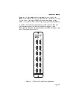
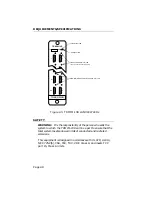
There are a number LANVIEW LEDs on the front panel of the
TRMIM-10R. The exact locations for these LEDs are illustrated in
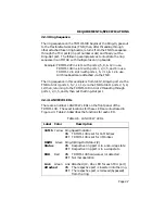
Figure 2-3. Table 2-6 describes the functions for each LED.
Table 2-6. LANVIEW LEDs
Label
Color
Description
16 Mb Yellow Ring Speed Indicator
ON
TRMIM-10R is set for 16 Mbit/sec
OFF TRMIM-10R is set for 4 Mbit/sec
RI/RO Green Ring-In/Ring-Out Status (2)
Status
ON
Respective ring port is in a non-wrap state
OFF Respective ring port is in a wrap state
ERR
Red
ON
TRMIM-10R hardware error detected
OFF Normal operation
Link
Green
Link Attached (10 - One LED for each TCU port)
Attached
ON
The respective port is inserted into the ring.
OFF The respective port is removed (bypassed)
from the ring.

