41
Step
No.
Description
Picture
1
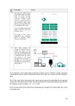
The
external
meter
is
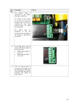
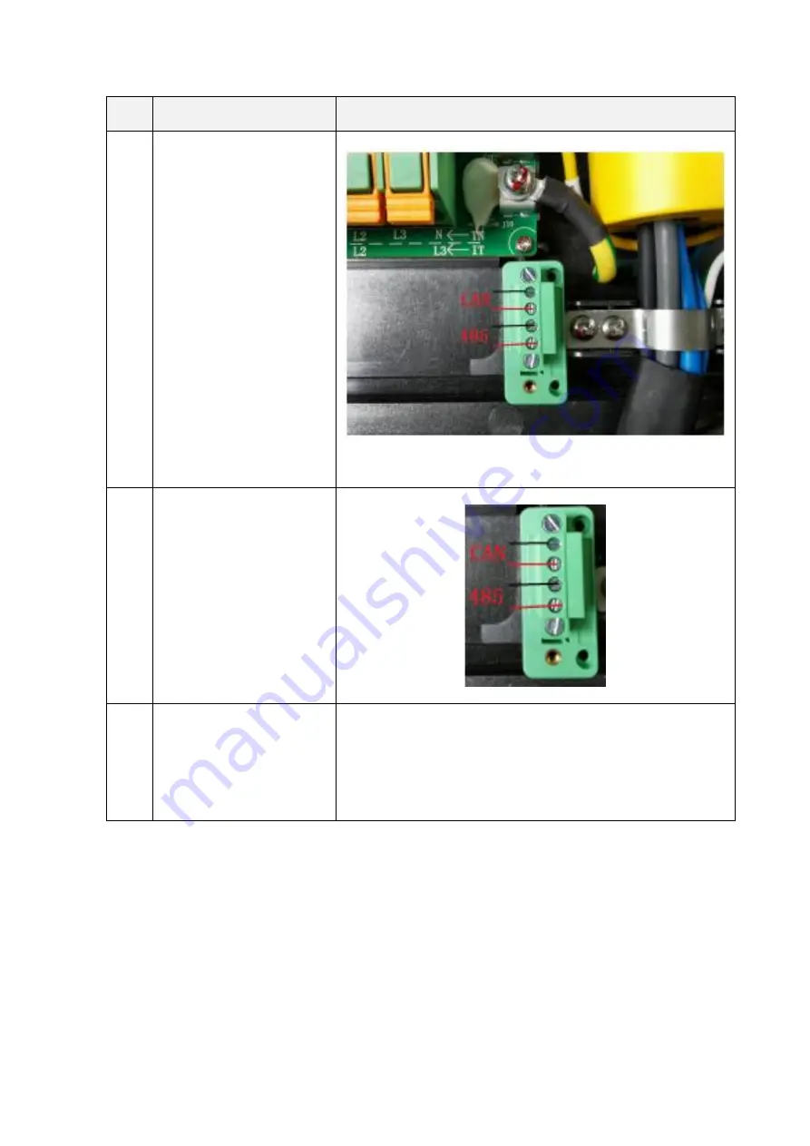
connected to the charger
through an RS-485 bus.
The RS-485 terminal blocks
can be reached removing the
charger cover and then by
removing the inner cover
which protects the supply
terminal blocks.
The
RS-485
wires
are
connected
to
the
bus
connector (terminal block) on
the charger as presented in
the picture.
2
The RS-485 signals from the
meter shall be connected as in
the picture where
•
RS-
485 positive signal “+”
is in “red”
•
RS-
485 negative signal “
-
“
is
in “black”
3
After the external meter is
connected, the charger must
be closed again with its covers.
This is extremely important for
functional and (mainly for
safety reasons


