background image

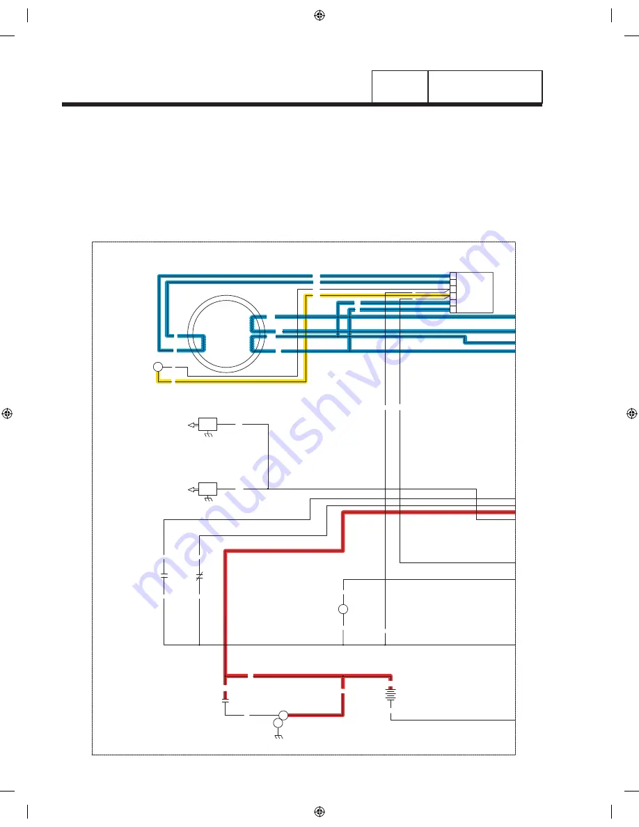
CONTROLLER DISPLAY

Running / Cooling Down

= 12 VDC ALWAYS PRESENT

= AC VOLTAGE

= GROUND FOR CONTROL PURPOSES

= 12 VDC DURING CRANKING ONLY

= 12 VDC DURING ENGINE RUN CONDITION

= DC FIELD EXCITATION

= 5 VDC TO LED

0

4

4

0

BA

6

11

22

6

2

2

REGULATOR

11

2
6
0
4

22

VOLTAGE

4

0

0

13

13

18

SP2

IM2

16

13

SCR

0

0

86

85

HTO

LOP

18

0

13

12V

BATTERY

SCR

SM

IM1

SP1

44

11

POWER

WINDING

33

22

WINDING

POWER

STATOR

4

0

56

0

SC

820
817
818

819

819

818

817

820

L2

L1

LED BOARD

4

3

2

1

4

ACTUATOR

GOVERNOR

14

14

90

OUTPUT

GENERATOR

240 VAC

NEUTRAL

INPUT

UTILITY

240 VAC

TRANSFER

+ BATTERY

GROUND

56

0

15B

23

23

0

0

FS

BATTERY WARMER

OPTIONAL

N1

00

22

33

11

44

CB

15B

14

0

0

CS

N2

N1

2

1

N2

N1

18

13

86

85

4

3

2

1

18

17

16

15

14

13

12

10

9

11

8

6 7

4

3

5

CB - CIRCUIT BREAKER, MAIN OUTPUT

HTO - HIGH TEMPERATURE SWITCH

FS - FUEL SOLENOID

LEGEND

SCR - STARTER CONTROL RELAY

SC - STARTER CONTACTOR

CS - CHOKE SOLENOID

LOP - LOW OIL PRESSURE SWITCH

SM - STARTER MOTOR

BA - BRUSH ASSEMBLY

IM_ - IGNITION MODULE

SP_ - SPARK PLUG

0

J3

J1

PRINTED CIRCUIT BOARD

TO

PCB

7.5 AMP FUSE

SELF RESETTING FUSE

CONTROLLER

J2

Page 114

utility VoltaGe reStored / re-tranSFer to utility

The  “Load”  is  powered  by  the  standby  power  supply. The  circuit  board  continues  to  seek  an  acceptable  utility 
source voltage. On restoration of utility source voltage, the following events will occur:

•  On restoration of utility source voltage above 75 percent of the nominal rated voltage, a “retransfer time delay” 

on the circuit board starts timing. The timer will run for about fifteen (15) seconds.

•  At the end of fifteen (15) seconds, the “retransfer time delay” will stop timing and circuit board action will open 

the Wire 23 circuit to ground. The transfer relay (TR) will then de-energize.

•  When  the  transfer  relay  (TR)  de-energizes,  its  normally-closed  contacts  close.  Utility  source  voltage  is  then 

delivered to the utility closing coil (C1), via Wires N1A/N2A, the closed TR contacts, Wire 126, limit switch XA1, 
and a bridge rectifier.

Part 4

DC CONTROL

sEctioN 4.2

oPEratioNal aNalYsis

0G9266revA.indd   114

10/15/2008   11:28:01 AM

Summary of Contents for FOR BYPASS AND FAN POWERED HUMIDIFIERS

Page 1: ...pair manual a u to m at i c s ta n d b y g e n e r ato r s Air Cooled Product 0G9266revA indd 1 10 15 2008 11 25 38 AM MODELS 7 kW NG 8 kW LP 9 kW NG 10 kW LP 13 kW NG 14 kW LP 16 kW NG 17 kW LP 18 kW...

Page 2: ...OTOR POLES Frequency RPM 2 x 60 x Frequency RPM 2 x 60 x Frequency RPM FREQUENCY RPM No of Rotor Poles RPM x Poles 2 x 60 RPM x Poles 2 x 60 RPM Frequency No of Rotor Poles 2 x 60 x Frequency Rotor Po...

Page 3: ...Drying The Generator 24 1 6 Engine Generator Protective Devices 25 General 25 Low Battery 25 Low Oil Pressure Shutdown 25 High Temperature Switch 25 Overspeed Shutdown 25 Rpm Sensor Failure 25 Overcra...

Page 4: ...own F1 or F2 Fuse 71 Problem 10 Units Starts And Transfer Occurs When Utility Power Is On 72 Problem 11 No Battery Charge Pre Packed Load Center 73 Problem 12 No Battery Charge RTSN RTSE Transfer Swit...

Page 5: ...Fuel Supply and Pressure 130 Test 67 Check Circuit Board Wire 14 Output 131 Test 68 Check Fuel Solenoid 132 Test 69 Check Choke Solenoid 132 Test 70 Check for Ignition Spark 134 Test 71 Check Spark P...

Page 6: ...o 77 F 25 C Maximum wattage and current are subject to and limited by such factors as fuel Btu content ambient temperature altitude engine power and condition etc Maximum power decreases about 3 5 per...

Page 7: ...GH 410 GT 530 GT 990 GT 999 Number of Cylinders 1 2 2 2 Rated Horsepower 3 600 rpm 14 8 18 32 34 Displacement 407cc 530cc 992cc 999cc Cylinder Block Aluminum w Cast Iron Sleeve Valve Arrangement Overh...

Page 8: ...1 2 LIFTING HOLES 4 CORNERS 642 25 3 731 9 28 8 637 6 25 1 1226 48 3 76 2 3 0 PEA GRAVEL MINIMUM 1218 47 9 1079 5 42 5 747 29 4 698 27 5 TRANSFER SWITCH 8KW 17KW IF SUPPLIED 207 8 2 299 11 8 997 39 3...

Page 9: ...REAR VIEW GROUNDING LUG CABLE ACCESS HOLE 250 0 9 8 446 6 17 6 378 7 14 9 44 8 1 8 530 0 20 9 575 3 22 7 FUEL INLET 12 20KW 1 2 NPT 8 10KW 3 4 NPT USE SUPPLIED ADAPTER REQUIRED FUEL PRESSURE NATURAL G...

Page 10: ...Battery Compartment Fuel Regulator Fuel Inlet back Air Filter Circuit Breakers GFCI Outlet All 17 20kW Control Panel Figure 1 3 12 14 16 17 and 20kW V twin GT 990 GT 999 Engine door removed 8kW Single...

Page 11: ...16 General 16 Fuel Requirements 16 Fuel Consumption 16 Reconfiguring The Fuel System 16 Engine Oil Recommendations 18 1 5 Testing Cleaning and Drying 19 Meters 19 The Vom 19 Measuring AC Voltage 19 M...

Page 12: ...us assemblies and systems work b assist the technician in finding the cause of malfunctions and c effect the expeditious repair of the equipment Item Number Many home standby generators are manufactur...

Page 13: ...y making a few adjustments for best operation and power LP propane gas is usually supplied as a liquid in pressure tanks Both the air cooled and the liquid cooled units require a vapor withdrawal type...

Page 14: ...Part 1 Page 12 General information Section 1 2 Installation basics Figure 1 Typical Installation 0G9266revA indd 12 10 15 2008 11 26 40 AM...

Page 15: ...andby generators are equipped with a termi nal board identified with the following terminals a UTILITY 1 b UTILITY 2 c 23 and d 15B Load centers house an identically marked terminal board When these f...

Page 16: ...generator the battery charger will be located in the generator on the side of the control assembly 2 Inside the Junction box between the generator and the transfer switch there will be 5 wires coming...

Page 17: ...transfer switch 3 Using the following diagram and UL approved wire nuts connect the following wires together Wire 0 will not be utilized for this setup Note Remove the battery charger from the trans...

Page 18: ...ns for proper installation Local codes will mandate correct routing of gaseous fuel line piping around gardens shrubs and other landscaping to prevent any damage Special considerations should be given...

Page 19: ...e generator MUST BE SUPPLIED FUEL SELECTION LEVER IN POSITION FOR NATURAL GAS Figure 2 10 kW GT 530 Inlet Hose Slid Back FUEL SELECTION LEVER OUT POSITION FOR LIQUID PROPANE VAPOR FUEL Figure 3 10 kW...

Page 20: ...ted operating temperature SAE 30 Above 32 F 10W 30 Between 40 F and 10 F Synthetic 5W 30 10 F and below Engine crankcase oil capacities for the engines cov ered in this manual can be found in the spec...

Page 21: ...s AC output voltage only at the unit s rated operating speed and AC frequency 2 The generator s Voltage Regulator can be adjusted for correct output voltage only while the unit is operating at its co...

Page 22: ...is usually requires the positive meter test lead to be connected to the correct amperes plug and the meter to be set to the amperes position Once the meter is properly set up to measure amperes the ci...

Page 23: ...MF that will cause a current of 1 ampere to flow through 1 ohm of resistance amPErE Unit measuring rate of current flow number of electrons past a given point oHm Unit measuring resistance or oppositi...

Page 24: ...1 SECOND Testing Stator Insulation All parts that might be damaged by the high meg ger voltages must be disconnected before testing Isolate all stator leads Figure 8 and connect all of the stator lead...

Page 25: ...the tester cord into a 120 volt AC wall socket and set its voltage selector switch to 1500 volts c Turn the tester switch ON and observe the breakdown lamp on tester DO NOT APPLY VOLTAGE LONGER THAN 1...

Page 26: ...ved The rotor must be completely isolated from other components before starting the test Attach all leads of all stator windings to ground 1 Connect the red tester lead to the positive slip ring neare...

Page 27: ...circuit board The run relay s normally open contacts will then open and a 12 volts DC power supply to a Wire 14 circuit will then be terminated This will result in closure of a fuel shutoff solenoid...

Page 28: ...control board will go into a rest cycle for seven 7 seconds then con tinue the rest of the crank cycle During a rest cycle the start and fuel outputs are de energized and the magneto output is shorted...

Page 29: ...E INJURY THAT MIGHT BE CAUSED BY SUCH STARTUP ALWAYS SET THE AUTO OFF MANUAL SWITCH TO ITS OFF POSITION BEFORE WORKING ON OR AROUND THIS EQUIPMENT 7 5 Amp Fuse This fuse protects the DC control circui...

Page 30: ...ansfer switch terminal lugs N1 and N2 2 pole 1 phase transfer switches 3 Set the generator AUTO OFF MANUAL switch to its AUTO position 4 Actuate the generator main line circuit breaker to its On or Cl...

Page 31: ...3 The 410cc engines have a choke behind the air box that is automatically controlled by the electronic control board Failure to Start This is defined as any of the following occurrences during cranki...

Page 32: ...utility if the generator is shut down for any reason such as the switch is in the OFF position or a shutdown alarm After transfer will shut down engine after one 1 minute cool down time 3 Exercise Wil...

Page 33: ...Load 39 Problem 5 Voltage and Frequency Drop Excessively When Loads are Applied 40 2 4 Diagnostic Tests 41 Introduction 41 Safety 41 Test 1 Check Main Circuit Breaker 41 Test 2 Check AC Output Voltage...

Page 34: ...board in the generator control panel Engine Generator Drive System The generator revolving field is driven by an air cooled horizontal crankshaft engine The generator is directly coupled to the engine...

Page 35: ...stem The rotor bearing is pressed onto the end of the rotor shaft The tapered rotor shaft is mounted to a tapered crankshaft and is held in place with a single through bolt Stator Assembly The stator...

Page 36: ...tage regulator rectifies that current and based on stator AC power winding sensing regulates it The rectified and regulated excitation current is then delivered to the rotor wind ings from the positiv...

Page 37: ...e all located on the circuit board Notice that field boost current is available only while the crank relay is energized i e while the engine is cranking Field boost voltage is reduced from that of bat...

Page 38: ...d to the voltage regulator via Wire 2 and Wire 6 Unregulated alternating current can flow from the wind ing to the regulator The voltage regulator senses AC power winding out put voltage and frequency...

Page 39: ...ACE REPAIR OR REPLACE REPAIR OR REPLACE THEN RETEST REPLACE VOLTAGE REGULATOR TEST 1 CHECK MAIN CIRCUIT BREAKER TEST 4 PERFORM FIXED EXCITATION ROTOR AMP DRAW PERFORM STATOR INSULATION RESISTANCE TEST...

Page 40: ...MP DRAW TEST 7 TEST STATOR TEST 7 TEST STATOR TEST 13 TEST ROTOR ASSEMBLY TEST 13 TEST ROTOR ASSEMBLY REPAIR OR REPLACE BAD GOOD GOOD GOOD GOOD GOOD GOOD GOOD GOOD BAD BAD BAD BAD BAD BAD BAD RE TEST...

Page 41: ...TO PROBLEM 2 8 10 kW UNITS 12 20 kW UNITS 12 20 kW UNITS 12 20 kW UNITS FREQUENCY AND VOLTAGE O K Problem 3 Generator Produces Low Voltage at No Load STOP TESTS Problem 4 Generator Produces High Volta...

Page 42: ...CONDITION NOT OVERLOADED GOOD ENGINE CONDITION GOOD DISCONTINUE TESTING LOOK FOR A SHORTED CONDITION IN A CONNECTED LOAD OR IN ONE OF THE LOAD CIRCUITS REDUCE LOADS TO UNIT S RATED CAPACITY BAD REPAI...

Page 43: ...uipment use common sense and remain alert at all times Never work on this equipment while you are physically or mentally fatigued If you don t understand a component device or system do not work on it...

Page 44: ...s with air cooled engine field boost current flow is available to the rotor only during engine cranking Test 4 Fixed Excitation Test Rotor Amp Draw Test DISCUSSION Supplying a fixed DC current to the...

Page 45: ...is test will verify the integrity of Wire 0 PROCEDURE 1 Set VOM to its R x 1 scale 2 Remove Wire 0 from the voltage regulator 4th terminal from the top Also voltage regulator is labeled next to termin...

Page 46: ...ranking the VOM should read approximately 4 6 Volts DC When engine is not crank ing VOM should indicate zero volts see Figure 3 6 Reconnect Wire 4 RESULTS 1 If normal field boost voltage is indicated...

Page 47: ...the other test lead to stator lead Wire 33 a The meter should read INFINITY b Any reading other than INFINITY indicates a short circuit between windings 16 Repeat Step 15 using stator lead Wire 11 Wir...

Page 48: ...Note the resistance reading and compare to the specifications in the front of this manual Note Wire 11 and Wire 44 could be switched on the main breaker If an INFINITY reading is indi cated try puttin...

Page 49: ...a voltage that is induced into the rotor If the DPE winding fails only residual magnetism of the rotor will be measured at the Main Breaker Note The resistance of stator windings is very low Some met...

Page 50: ...the brush assem bly Connect one meter test lead to Wire 0 Connect the other test lead to Wire 0 at the voltage regulator CONTINUITY should be measured If INFINITY is measured repair or replace Wire 0...

Page 51: ...The unit s AC output voltage is proportional to the AC frequency For example a unit rated 240 volts line to line will supply that rated voltage plus or minus 2 percent at a frequency of 60 Hertz If fo...

Page 52: ...ough it s travel 3 Physically move the throttle to the closed position by pulling the stepper motor arm towards the idle stop See Figures 11 and 12 for 9 10 kW units or Figure 13 for 12 20 kW Units 4...

Page 53: ...Twin Engine Units With the frequency at 60 Hertz slowly turn the slotted potentiometer Figure 15 until line voltage reads 247 249 volts NOTE The access panel on top of the control panel must be remov...

Page 54: ...engine speed and frequency drop excessively under load the engine may be under powered An under powered engine can be the result of a dirty air cleaner loss of engine compression faulty fuel set tings...

Page 55: ...s charged before testing A capacitor can be discharged by crossing the terminals with a metal insulated screw driver Danger Use proper protective equipment when dealing with a capacitor that has explo...

Page 56: ...Page 54 NOTES 0G9266revA indd 54 10 15 2008 11 27 21 AM...

Page 57: ...s E1 E2 74 Test 27 Check Manual Transfer Switch Operation 75 Test 28 Check 23 And 15B Wiring Connections 76 Test 29 Test Transfer Relay TR 77 Test 30 Standby Control Circuit 78 Test 31 Check Wire 23 7...

Page 58: ...ITEMS 32 37 38 18 27 3A 3B 13 8 14 12 39 20 15 19 26 26 2 3 5 11 6 4 9 7 10 24 23 16 21 22 22 9 16 23 29 1 30 ITEM DESCRIPTION 1 GTS LOAD CENTER ENCLOSURE 2 COVER GTS LOAD CTR 3 TRANSFER SWITCH HOME...

Page 59: ...te the transfer action to Standby This coil s bridge rectifier is also sealed in the coil wrappings Replace the coil and bridge rectifier as a unit LIMIT SWITCHES SW2 AND SW3 Switches are mechanically...

Page 60: ...to energize that coil c Retransfer back to UTILITY occurs Neutral Lug The standby generator is equipped with an UNGROUNDED neutral The neutral lug in the transfer switch is isolated from the switch e...

Page 61: ...y in Section 3 1 Fuse Holder The fuse holder holds three 3 fuses designated as fuses F1 F2 and F3 Each fuse is rated 5 amperes FUSES F1 F2 These two fuses protect the UTILITY 1 and UTILITY 2 circuit a...

Page 62: ...CONTROL PANEL A B SW1 LC CIRCUIT 9 CIRCUIT 6 CIRCUIT 5 CIRCUIT 2 CIRCUIT 1 CIRCUIT 3 CIRCUIT 4 CIRCUIT 7 CIRCUIT 8 CIRCUIT 11 CIRCUIT 12 CIRCUIT 13 CIRCUIT 14 CIRCUIT 16 CIRCUIT 15 14 CIRCUIT LOAD CE...

Page 63: ...CE ONLY SW1 AUTOMATIC TRANSFER SWITCH C2 GENERATOR COIL RECTIFIER C1 UTILITY COIL RECTIFIER F1 F2 F3 5A 600V FUSE TB1 TERMINAL STRIP SW2 SW3 LIMIT SWITCHES TR1 TRANSFER RELAY N NEUTRAL BLK E1 RED RED...

Page 64: ...COIL RECTIFIER SW1 AUTOMATIC TRANSFER SWITCH 16 CIRCUIT SHOWN FOR REFERENCE ONLY LC CIRCUIT BREAKER LOADS LEGEND SENSING UTILITY INSIDE GROUND GREEN GROUND GREEN UTILITY GENERATOR GROUND DC Utility So...

Page 65: ...SW3 LIMIT SWITCHES TB1 TERMINAL STRIP F1 F2 F3 5A 600V FUSE C1 UTILITY COIL RECTIFIER C2 GENERATOR COIL RECTIFIER SW1 AUTOMATIC TRANSFER SWITCH 16 CIRCUIT SHOWN FOR REFERENCE ONLY LC CIRCUIT BREAKER L...

Page 66: ...L WHITE NEUTRAL WHITE 23 0 F1 N2 N1 15B 23 BLACK RED N2 N1 15B 240VAC TO TO GENERATOR OUTPUT PANEL MAIN DISTRIBUTION T1 T2 T1 T2 E2 E2 E2 E2 E1 E1 N1A N1A N2A N2A B B B B B E1 E1 E1 N1A N1A N1A 15B 23...

Page 67: ...UTION T1 T2 T1 T2 E2 E2 E2 E2 E1 E1 N1A N1A N2A N2A B B B B B E1 E1 E1 N1A N1A N1A 15B 23 E1 E2 205 205 126 126 E2 N1A N2A N2A A N2A 240VAC OUTPUT GENERATOR TS TO CONTROL PANEL A B SW1 LC CIRCUIT 9 CI...

Page 68: ...AC OUTPUT GENERATOR TS TO CONTROL PANEL A B SW1 LC CIRCUIT 9 CIRCUIT 6 CIRCUIT 5 CIRCUIT 2 CIRCUIT 1 CIRCUIT 3 CIRCUIT 4 CIRCUIT 7 CIRCUIT 8 CIRCUIT 11 CIRCUIT 12 CIRCUIT 13 CIRCUIT 14 CIRCUIT 16 CIRC...

Page 69: ...A N1A N1A 15B 23 E1 E2 205 205 126 126 E2 N1A N2A N2A A N2A 240VAC OUTPUT GENERATOR TS TO CONTROL PANEL A B SW1 LC CIRCUIT 9 CIRCUIT 6 CIRCUIT 5 CIRCUIT 2 CIRCUIT 1 CIRCUIT 3 CIRCUIT 4 CIRCUIT 7 CIRCU...

Page 70: ...N1A N2A N2A B B B B B E1 E1 E1 N1A N1A N1A 15B 23 E1 E2 205 205 126 126 E2 N1A N2A N2A A N2A 240VAC OUTPUT GENERATOR TS TO CONTROL PANEL A B SW1 LC CIRCUIT 9 CIRCUIT 6 CIRCUIT 5 CIRCUIT 2 CIRCUIT 1 C...

Page 71: ...A N2A A N2A 240VAC OUTPUT GENERATOR TS TO CONTROL PANEL A B SW1 LC CIRCUIT 9 CIRCUIT 6 CIRCUIT 5 CIRCUIT 2 CIRCUIT 1 CIRCUIT 3 CIRCUIT 4 CIRCUIT 7 CIRCUIT 8 CIRCUIT 11 CIRCUIT 12 CIRCUIT 13 CIRCUIT 14...

Page 72: ...ce of each test BAD BAD REPAIR OR REPLACE AS NEEDED REPLACE GOOD GOOD GOOD FIND CAUSE OF NO AC OUTPUT TO TRANSFER SWITCH FROM GENERATOR TEST 26 CHECK VOLTAGE AT TERMINAL LUGS E1 E2 TEST 27 CHECK MANUA...

Page 73: ...in Manual Mode BAD BAD REPAIR OR REPLACE AS NEEDED REPAIR OR REPLACE AS NEEDED REPLACE GOOD GOOD GOOD TEST 27 CHECK MANUAL TRANSFER SWITCH OPERATION TEST 31 CHECK WIRE 23 BAD TEST 32 CHECK UTILITY CON...

Page 74: ...arts and Transfer Occurs When Utility Power Is On 8 kW Green LED Flashes 10 20 kW Status Utility Lost TEST 37 CHECK UTILITY SENSING VOLTAGE AT CIRCUIT BOARD TEST 36 CHECK N1 N2 VOLTAGE TEST 38 CHECK U...

Page 75: ...R REPLACE BAD BAD NO BATTERY SUPPLY VOLTAGE REPLACE PRINTED CIRCUIT BOARD REPAIR OR REPLACE REPLACE CHARGER Problem 13 No Battery Charge GenReady Load Center TEST 46 CHECK BATTERY CHARGER SUPPLY VOLTA...

Page 76: ...On or Closed position After confirming that the generator main circuit breaker is set to ON or closed check the voltage at transfer mechanism Terminal Lugs E1 and E2 with an accurate AC voltmeter or...

Page 77: ...ng coil terminals but transfer to Standby does not occur the cause of the failure may be a a failed standby closing coil and or bridge rectifier or b a seized or sticking actuating coil or load contac...

Page 78: ...fuse F3 from the transfer switch to disable the battery charge circuit Caution After removing the fuse from the bat tery charger wait 5 minutes before proceeding 5 Set VOM to measure DC voltage 6 Con...

Page 79: ...hms Connect one meter test lead to Wire 15B at the control panel terminal strip Connect the other meter test lead to Wire 15B Pin Location J2 8 Continuity should be measured a If continuity is not mea...

Page 80: ...e across points A and E 240 VAC should be measured a If 240 VAC is not measured replace transfer relay b If 240 VAC is measured proceed to Step 9 9 Measure across points A and F 240 VAC should be meas...

Page 81: ...ction 3 4 Diagnostic tests Part 3 Page 79 A B 7 9 4 6 1 3 TR1 SW1 205 C2 SW3 E1 SW2 C1 1 2 1 2 N1 N2 E1 E2 E2 T1 T2 B A G E F C D H Figure 4 Standby Control Circuit Test Points 0G9266revA indd 79 10 1...

Page 82: ...fer switch customer connection side see Figure 6 GENERATOR TERMINAL STRIP CUSTOMER SIDE N1 N2 CONTROL BOARD CONNECTION 0 N1 N2 15B 23 Figure 6 Transfer Relay Test Points 9 Disconnect the J2 connector...

Page 83: ...Points Transfer switch Section 3 4 Diagnostic tests Part 3 Page 81 N1A N1A A B 7 9 4 6 1 3 TR1 SW1 B C2 SW3 SW2 C1 A N2A N2A F1 F2 F3 A A A B B B 1 2 1 2 N1 N2 E1 E2 T1 T2 126 A B I G C D E F H 0G926...

Page 84: ...SION The limit switches are wired to the normally closed contacts When the switches are activated the contacts open PROCEDURE With the generator shut down the generator main circuit breaker turned OFF...

Page 85: ...e negative meter lead to Wire 0 at the terminal strip INFINITY should be measured e Connect the negative meter lead to Wire N2 at the terminal block INFINITY should be measured f Connect the negative...

Page 86: ...s controlled by the circuit board A zero or low voltage at these terminals will also prevent retransfer back to the Utility source Procedure With utility source voltage available to terminal lugs N1 a...

Page 87: ...UTILITY COIL RECTIFIER F1 F2 F3 5A 600V FUSE TB1 TERMINAL STRIP N NEUTRAL SW1 B C2 SW3 SW2 A C1 F1 F2 F3 A A A B B B 0 0 BLK WIRE RED WIRE 15B 1 2 3 T1 BC 1 2 1 2 N1 N2 E1 E2 T1 T2 BC BATTERY CHARGER...

Page 88: ...ltage 2 Remove Wire 0 and Wire 15B from transfer switch terminal strip points F and G 3 Measure across points H and I Battery supply voltage 12 VDC should be measured a If battery voltage is not measu...

Page 89: ...s E and F 120 VAC should be measured a If 120 VAC is not measured repair or replace supply wires BC line and BC 00 b If 120 VAC is measured refer to flow chart TEST 44 CHECK BATTERY CHARGER OUTPUT VOL...

Page 90: ...ODE NEUTRAL BLOCK DISTRIBUTION PANEL GROUND BC LINE BC 00 5 AMP FUSE T1 T2 CUSTOMER LOAD RTS TRANSFER SWITCH T1 T2 E1 C2 VR2 STANDBY E1 E2 C1 VR1 UTILITY N1 N2 N2 N1 C D E A B H G F 23 15B 0 N1 N2 H G...

Page 91: ...INE TO GROUNDING ELECTRODE SERVICE DISCONNECT ATS 23 E1 E2 BC LINE BC 00 FUSE N2 N1 5 AMP SOCKET METER UTILITY PANELBOARD 15B T1 T2 E1 E2 N2 N1 C D E A B H G F DETAIL DETAIL 23 15B 0 N1 N2 H G Figure...

Page 92: ...120 VAC should be measured a If 120 VAC is not measured verify that load source voltage is available and that the duplex circuit breaker in ON b If 120 VAC is measured proceed to Step 3 3 Measure acr...

Page 93: ...OAD CENTER DUPLEX BREAKER BC 00 UTILITY SOCKET METER ENGINE GENERATOR N1 WHITE GREEN BC 00 N2 15B 23 0 E1 E2 BC LINE C D E A B F DETAIL DETAIL DETAIL DETAIL BC 00 BC LINE N1 N2 15B 23 0 E F C D Figure...

Page 94: ...R SUPPLY VOLTAGE Load Shed Transfer Switch DISCUSSION The battery charger is supplied with 120 VAC The output of the battery charger is 13 4 VDC 2 5A PROCEDURE Refer to Figure 14 1 Set VOM to measure...

Page 95: ...SOLENOID COIL STANDBY CLOSING BATTERY CHARGER F1 F2 C1 C1A C2A C2 ATS BC LEGEND C2A T2 T1 XB1 XA1 C1A LSS E2 E1 N2 N1 C2 T1 T2 ATS XB1 E1 C1 XA1 N1 E2 N2 NB WHT CONNECTION CUSTOMER 0 15B 23 S1 3 2 1 J...

Page 96: ...r or replace Wire 0 or Wire 15B between the generator terminal strip and the ground lug b If 12 VDC is not measured proceed to Step 5 8 Set VOM to measure resistance 9 Connect the meter test leads acr...

Page 97: ...uto Off Manual Switch 123 Test 57 Try a Manual Start 123 Test 58 Auto Off Manual Switch V Twin Only 123 Test 59 Test Auto Operations 124 Test 60 Check 7 5 Amp Fuse 124 Test 61 Check Battery 124 Test 6...

Page 98: ...and exercises the generator once every seven days Provides automatic engine shutdown in the event of low oil pressure high oil temperature overspeed no RPM sense overcrank or low battery An 18 pin an...

Page 99: ...9 CIRCUIT BREAKER 10 20 KW 10 LED DISPLAY Figure 3 Control Panel Component Identification DC control Section 4 1 Description and components Part 4 Page 97 7 5 Amp Fuse This fuse protects the circuit b...

Page 100: ...o reach the battery from the battery charger Provides 12VDC to the Transfer Relay J2 9 NOT USED J2 10 0 Common Ground J2 11 56 12 VDC output to starter contactor for single cylinder engines J2 15 NOT...

Page 101: ...attery from the battery charger Provides 12 VDC to the Transfer Relay J2 9 820 Positive voltage 5 VDC for status LEDs J2 10 0 Common Ground J2 11 56 12 VDC output to starter contactor relay for V Twin...

Page 102: ...uel solenoid and choke solenoid operation J2 4 817 Grounded by printed circuit board to turn on System Ready Green LED J2 5 23 Switched to ground for transfer relay operation J2 6 NOT USED J2 7 NOT US...

Page 103: ...ransfer Relay J2 9 820 Positive voltage 5 VDC for status LEDs J2 10 0 Common Ground J2 11 56 12 VDC output to starter contactor relay for V Twin engines J2 12 4 Field Boost output J2 13 818 Grounded b...

Page 104: ...elected there may be a list of choices pre sented Use the same navigation method to select the desired screen refer to the Menu System diagram Changing Settings Edit Menu To change a setting such as d...

Page 105: ...er 60 Hz The possible Status messages of the display are as follows s 3WITCHED FF 4IME ATE s 2EADY TO 2UN 4IME ATE s 5TILITY OSS ELAY 0AUSING FOR 8 3ECONDS s RANKING TTEMPT 8 s 2UNNING IN XERCISE 4IME...

Page 106: ...the DC control system on units with air cooled engine A thorough understanding of how the system works is essential to sound and logical troubleshooting The DC control system illustrations on the foll...

Page 107: ...NOID LOP LOW OIL PRESSURE SWITCH SM STARTER MOTOR BA BRUSH ASSEMBLY IM_ IGNITION MODULE SP_ SPARK PLUG 0 J3 J1 PRINTED CIRCUIT BOARD TO PCB 7 5 AMP FUSE SELF RESETTING FUSE CONTROLLER J2 Section 4 2 O...

Page 108: ...igure 2 below Should a Utility power source failure occur circuit condition may be briefly described as follows The circuit board constantly senses for an acceptable Utility source voltage via transfe...

Page 109: ...EL SOLENOID LEGEND SCR STARTER CONTROL RELAY SC STARTER CONTACTOR CS CHOKE SOLENOID LOP LOW OIL PRESSURE SWITCH SM STARTER MOTOR BA BRUSH ASSEMBLY IM_ IGNITION MODULE SP_ SPARK PLUG 0 J3 J1 PRINTED CI...

Page 110: ...ity voltage is still below 65 percent of nominal circuit board action will energize the circuit board s crank and run relays simultaneously Printed circuit board action delivers 12 volts DC to a start...

Page 111: ...MBLY IM_ IGNITION MODULE SP_ SPARK PLUG 0 J3 J1 PRINTED CIRCUIT BOARD TO PCB 7 5 AMP FUSE SELF RESETTING FUSE CONTROLLER J2 Page 109 Section 4 2 Operational analysis Figure 3 Circuit Condition Engine...

Page 112: ...and ignition occurring the engine starts Engine startup and running may be briefly described as follows Voltage pulses from the ignition magnetos are delivered to the circuit board via Wire 18 Once t...

Page 113: ...OL RELAY SC STARTER CONTACTOR CS CHOKE SOLENOID LOP LOW OIL PRESSURE SWITCH SM STARTER MOTOR BA BRUSH ASSEMBLY IM_ IGNITION MODULE SP_ SPARK PLUG 0 J3 J1 PRINTED CIRCUIT BOARD TO PCB 7 5 AMP FUSE SELF...

Page 114: ...ugs E1 and E2 and to the open contacts on the transfer relay Initial transfer to the STANDBY power supply may be briefly described as follows 12 volts DC output is delivered to the transfer relay TR a...

Page 115: ...PCB 7 5 AMP FUSE SELF RESETTING FUSE J2 Page 113 Section 4 2 Operational analysis Figure 5 Circuit Condition Initial Transfer to Standby When the circuit board s engine warm up timer times out circui...

Page 116: ...urce voltage above 75 percent of the nominal rated voltage a retransfer time delay on the circuit board starts timing The timer will run for about fifteen 15 seconds At the end of fifteen 15 seconds t...

Page 117: ...5 VDC TO LED 820 817 818 819 819 818 817 820 L2 L1 LED BOARD 4 3 2 1 4 ACTUATOR GOVERNOR 14 14 90 OUTPUT GENERATOR 240 VAC NEUTRAL INPUT UTILITY 240 VAC TRANSFER BATTERY GROUND 56 0 15B 23 23 0 0 FS B...

Page 118: ...ce an engine cool down timer on the circuit board starts timing When that timer has timed out approximately one minute circuit board action will de energize the circuit board s run relay The following...

Page 119: ...6 7 4 3 5 CB CIRCUIT BREAKER MAIN OUTPUT HTO HIGH TEMPERATURE SWITCH FS FUEL SOLENOID LEGEND SCR STARTER CONTROL RELAY SC STARTER CONTACTOR CS CHOKE SOLENOID LOP LOW OIL PRESSURE SWITCH SM STARTER MO...

Page 120: ...good practice to check the engine for freedom of rotation by removing the spark plugs and turning the crankshaft over slowly by hand to be sure it rotates freely WARNING DO NOT ROTATE ENGINE WITH ELE...

Page 121: ...HECK ENGINE COMPRESSION TEST 68 CHECK FUEL SOLENOID TEST 67 CHECK CIRCUIT BOARD WIRE 14 OUTPUT GOOD GOOD GOOD GOOD GOOD GOOD GOOD GOOD GOOD GOOD GOOD BAD BAD BAD BAD BAD BAD BAD BAD BAD BAD REPAIR OR...

Page 122: ...GLE CYLINDER UNITS V TWIN UNITS TEST 66 CHECK FUEL SUPPLY AND PRESSURE IF RECONFIGURED TO LP GAS VERIFY THAT PROPER PROCEDURE WAS FOLLOWED REFER TO SECTION 1 3 TEST 70 CHECK FOR IGNITION SPARK TEST 74...

Page 123: ...78 CHECK WIRE 18 CONTINUITY TEST 14 CHECK AC OUTPUT FREQUENCY CHECK FAULT LIGHTS BAD BAD Problem 19 Shutdown Alarm Fault Occured TEST 75 CHECK OIL PRESSURE SWITCH AND WIRE 86 TEST 76 CHECK HIGH OIL TE...

Page 124: ...RUNNING CIRCUITS Problem 21 Generator Will Not Exercise TEST 79 TEST EXERCISE FUNCTION GOOD BAD Problem 22 No Low Speed Exercise TEST 81 CHECK TO SEE IF LOW SPEED FUNCTION IS ENABLED TEST 82 CHECK OP...

Page 125: ...operation is obtained discontinue tests 2 If engine does not crank when utility power is turned off proceed to Problem 15 Flow Chart Section 4 3 3 If engine cranks but won t start go to Problem 17 in...

Page 126: ...ator does not perform the sequence of events listed in the above discussion replace the printed circuit board Results Refer back to flow chart Test 60 Check 7 5 Amp Fuse DISCUSSION The 7 5 amp fuse is...

Page 127: ...rage reading of 1 200 means the battery is 50 charged d An average reading of 1 170 indicates the bat tery is 25 charged CHECK EACH CELL AFTER CHARGING USE A TEMPERATURE COMPENSATED HYDROMETER Figure...

Page 128: ...ress Enter f Digital Output 6 is Wire 56 output from the board Refer to Figure 6 5 Actuate the AUTO OFF MANUAL switch to the MANUAL position and observe digital output Number 6 If the printed circuit...

Page 129: ...must close or the engine will not crank This test will determine if the starter contactor is in working order PROCEDURE Carefully inspect the starter motor cable that runs from the battery to the star...

Page 130: ...fully charged Set a VOM to measure DC voltage 12 VDC Connect the meter positive test lead to the starter contactor stud which has the small jumper wire connected to the starter Connect the common test...

Page 131: ...omobile diagnostic service supplier METAL STOCK 1 4 THICK STEEL 12 1 0 4 2 2 625 3 5 0 5 0 5 DRILL TWO HOLES 1 2 FOR STARTER MOUNTING BRACKET DRILL TWO HOLES 1 2 FOR MOUNTING TACHOMETER TAP FOR 1 4 20...

Page 132: ...ollowing installation and periodically thereafter No leakage is permitted Leak test methods must comply strictly with gas codes DANGER GASEOUS FUELS ARE HIGHLY EXPLOSIVE DO NOT USE FLAME OR HEAT TO TE...

Page 133: ...d energizes open to allow fuel flow to the engine This test will determine if the circuit board is working properly Procedure 12 20 kW Units 1 Set the AUTO OFF MANUAL switch to OFF 2 Set a VOM to meas...

Page 134: ...gas pressure is not measured repair or replace the fuel solenoid Procedure 10 kw Units 1 Remove the hose from fuel solenoid FS2 and install a manometer to Port 2 on the fuel regulator See Figure 19 2...

Page 135: ...choke solenoid Male Side Connect the negative test lead to Wire 90 Pin 2 Approximately 3 7 ohms should be measured 7 With the generator running at a speed of approximately 60 Hertz verify that the ch...

Page 136: ...est 70 Check for Ignition Spark DISCUSSION If the engine cranks but will not start perhaps an ignition system failure has occurred A special spark tester can be used to check for ignition spark PROCED...

Page 137: ...ngine A spark miss will be readily apparent If spark jumps the spark tester gap regularly but the engine miss continues the problem is in the spark plug or in the fuel system NOTE A sheared flywheel k...

Page 138: ...h and solvent 2 Replace any spark plug having burned electrodes or cracked porcelain 3 Set gap on new or used spark plugs as follows Engine Size kW Rating Plug Gap Recommended Plug 410 cc 8 kW 0 030 i...

Page 139: ...difficult to obtain an accu rate compression reading without special equip ment For that reason compression values are not published for the V Twin engine Testing has proven that an accurate compress...

Page 140: ...ght be the ignition magneto s This test consists of checking ohm values across the primary and secondary windings of the magneto and adjusting the air gap between the ignition magneto s and the flywhe...

Page 141: ...netos Note If gap is only adjusted ensure to properly test the magnetos by cranking the engine over before reassembly occurs Spark should be present on both cylinders before reassembly should be compl...

Page 142: ...is the front cylinder Figure 37 Figure 36 Cylinder One Back Short Figure 37 Cylinder Two Front Long 4 When installing new magnetos there will be one with a short plug wire and one with a longer plug w...

Page 143: ...el a Check engine oil level b If necessary add the recommended oil to the dipstick FULL mark DO NOT OVERFILL ABOVE THE FULL MARK 3 With oil level correct try starting the engine a If engine still cran...

Page 144: ...se 2 Check the installation and area surrounding the generator There should be at least three feet of clear area around the entire unit Make sure that there are no obstructions preventing incoming and...

Page 145: ...via Wire 18 This signal has an AC voltage of 4 6 volts on V Twin engines only If this signal is not received by the printed circuit board the unit will shut down due to no RPM sensing Procedure V Twi...

Page 146: ...top The generator will start and run for approximately 12 minutes and then shutdown on it s own The exerciser will then be set to start and run at that time of that day each week If the unit does not...

Page 147: ...round between the J2 Connector and SC or CS repair or replace the shorted wire 5 Disconnect Wire 56 from the Starter Contactor Relay SCR Disconnect the Choke Solenoid CS connector a Connect one meter...

Page 148: ...ound Check brushes slip rings and rotor Test 81 Check to see if Low Speed Function is enabled Discussion The Low speed exercise function when it is enabled allows the generator to exercise at 2400 rpm...

Page 149: ...nts Part Title 5 1 System Functional Tests 5 1 System Functional Tests 148 Introduction 148 Manual Transfer Switch Operation 148 Electrical Checks 148 Generator Tests Under Load 149 Checking Automatic...

Page 150: ...enclosure 5 Place open end of the manual transfer handle over transfer switch operating lever 6 To connect LOAD terminal lugs to the utility power source move the handle upward 7 To connect LOAD termi...

Page 151: ...OFF MANUAL switch to OFF The engine should shut down NOTE It is important that you do not proceed until you are certain that generator AC voltage and fre quency are correct and within the stated limi...

Page 152: ...d then shuts down Transfer of loads to the generator output does not occur during the exercise cycle unless utility power is lost Procedure 8 kW Units A switch on the control panel see Figure 3 1 perm...

Page 153: ...andby Generators Page 151 Table of contents Part Title 6 1 Major Disassembly 6 1 Major Disassembly 152 Front Engine Access 152 Major Disassembly 156 Torque Requirements Unless Otherwise Specified 162...

Page 154: ...ngine Access 1 Remove Controls Cover Using a Torx T 27 socket remove two bolts and ground washer from the controls cover Remove the controls cover See Figure 2 Figure 2 2 Remove controller Using a Phi...

Page 155: ...6 Figure 5 Figure 6 6 Remove controller mounting box Using an 8mm socket remove the two screws from the rear of the control ler mounting box See Figure 7 Using a 10mm socket remove the two bolts from...

Page 156: ...of the regulator Using a 10mm socket remove one 10mm bolt from the base of the plenum and one 10mm bolt from the base of the fuel regulator Flex the enclosure side out to allow for room to remove the...

Page 157: ...hile removing the airbox remove the four rubber washers See Figure 16 Figure 15 Figure 16 13 Unbolt Oil Cooler Using a 10mm socket remove the two 10mm bolts from the front of the oil cooler See Figure...

Page 158: ...20 and four 10mm bolts from the left side of the blower housing See Figure 21 Remove blower housing Figure 19 Figure 20 Figure 21 Major Disassembly Safety 1 Set the AUTO OFF MANUAL switch to OFF 2 Re...

Page 159: ...socket remove the two bolts from the exhaust flex pipe cover Remove the cover See Figure 25 Figure 25 4 Remove Exhaust Flex Pipe Using a socket remove the front and rear muffler clamp Slide exhaust f...

Page 160: ...loosen the bottom bolt See Figure 29 Holding the roof remove the bottom hinge bolt remove the side panel by sliding it forward then re install the hinge bolt Figure 28 Figure 29 7 Remove Fan Housing C...

Page 161: ...move Brushes Using a 7mm socket remove brushes See Figure 33 Figure 33 11 Remove Alternator Divider Panel Using a 10mm socket remove two bottom base bolts Using a T27 torx driver remove one top rear b...

Page 162: ...rom main bea kers See Figure 37 Figure 37 15 Alternator Air Intake Bellows Removal Remove alterna tor intake bellows See Figure 38 Figure 38 16 Rear Bearing Carrier Removal Using a 13mm socket remove...

Page 163: ...d use a screw driver to screw it into the crankshaft Use a 3 M12x1 75 bolt to screw into rotor Apply torque to the 3 M12x1 75 bolt until taper breaks See Figure 43 Figure 42 11 Remove Engine Using a 1...

Page 164: ...50 in lbs M6 1 0 TAPTITE SCREW INTO ALUMINUM 50 96 in lbs M6 1 0 TAPTITE SCREW INTO PIERCED HOLE 50 96 in lbs M6 1 0 TAPTITE SCREW INTO WELDNUT 50 96 in lbs M8 1 25 TAPTITE SCREW INTO ALUMINUM 12 18...

Page 165: ...iagram 10 kW HSb 0G8512 Schematic 10 kW HSb 0G7947 Wiring Diagram 14 kW HSb 0G8513 Schematic 14 kW HSb 0G7948 Wiring Diagram 17 kW HSb 0G8514 Schematic 17 kW HSb 0G8186 Wiring Diagram 20 kW HSb 0G8515...

Page 166: ...RED 1 2 BLK FRAME GND 0 ENGINE GND 0 18 10 10 10 10 N1 N2 1 2 N1 N2 6 6 PANEL GND 0 0 0 0 0 0 GROUND BATTERY TRANS SIG 0 15B 23 15B 23 0 14 0 N1 CAPACITOR SC SM 13 16 13 0 56 56 56 0 0 56 0 GROUP G W...

Page 167: ...ISE 300V UL LISTED UNLESS NOTE ALL WIRES 18 AWG OPTIONAL 0 LEGEND CB CIRCUIT BREAKER MAIN OUTPUT GND GROUND HTO HIGH TEMPERATURE SWITCH IM1 IGNITON MODULE LOP LOW OIL PRESSURE SWITCH SC STARTER CONTAC...

Page 168: ...CAPACITOR 44 11 POWER WINDING 33 22 WINDING POWER STATOR N2 N1 2 1 N2 N1 18 13 86 85 4 3 2 1 J1 PRINTED CIRCUIT BOARD CONTROLLER J2 18 17 16 15 14 13 12 10 9 11 8 6 7 4 3 5 SM CB CIRCUIT BREAKER MAIN...

Page 169: ...Data Schematic 8 kW Home Standby Part 7 Page 167 PAGE LEFT PLANK INTENTIONALLY GROUP G SCHEMATIC DIAGRAM 2008 AIR COOLED DRAWING 0G8511 REVISION A DATE Drawing 0G8511 0G9266revA indd 167 10 15 2008 1...

Page 170: ...R SC SM FRAME GND 0 ENGINE GND 0 18 13 14 90 0 0 56 A 0 B SCR 16 13 16 10 10 10 10 1 2 N1 N2 0 6 6 PANEL GND 0 0 0 0 0 0 GROUND BATTERY TRANS SIG 0 15B 23 15B 23 0 14 14 0 820 817 818 N1 CAPACITOR 819...

Page 171: ...OPTIONAL FUEL SOLENOID 0 14 819 20 L3 RED ALARM L1 GREEN SYSTEM READY L3 L1 LED BOARD 4 3 2 1 0 LEGEND CB CIRCUIT BREAKER MAIN OUTPUT GND GROUND HTO HIGH TEMPERATURE SWITCH IM_ IGNITON MODULE LOP LOW...

Page 172: ...TOR 44 11 POWER WINDING 33 22 WINDING POWER STATOR N2 N1 2 1 N2 N1 18 13 86 85 4 3 2 1 J1 PRINTED CIRCUIT BOARD CONTROLLER J2 18 17 16 15 14 13 12 10 9 11 8 6 7 4 3 5 L1 L2 820 817 818 819 CB CIRCUIT...

Page 173: ...ectrical Data Schematic 10 kW Home Standby Part 7 PAGE LEFT BLANK INTENTIONALLY GROUP G SCHEMATIC DIAGRAM 2008 AIR COOLED DRAWING 0G8512 REVISION A DATE Drawing 0G8512 0G9266revA indd 171 10 15 2008 1...

Page 174: ...A 0 B SCR 16 13 16 N1 N2 1 2 N1 N2 0 6 6 PANEL GND 0 0 0 0 0 0 0 0 GROUND BATTERY TRANS SIG 0 15B 23 15B 23 0 14 14 0 820 817 818 819 N1 CLOSEST TO BEARING BA 0 4 6 22 11 44 22 33 11 STATOR 2 0 6 VOL...

Page 175: ...ES 18 AWG OPTIONAL L3 RED ALARM L1 GREEN SYSTEM READY L3 L1 LED BOARD 4 3 2 1 LEGEND BA BRUSH ASSEMBLY CB CIRCUIT BREAKER MAIN OUTPUT GND GROUND HTO HIGH TEMPERATURE SWITCH IM_ IGNITON MODULE LOP LOW...

Page 176: ...1 2 6 0 4 22 VOLTAGE 4 0 0 13 13 18 SP2 IM2 16 13 SCR 0 0 86 85 HTO LOP 18 0 13 12V BATTERY SCR SM IM1 SP1 44 11 POWER WINDING 33 22 WINDING POWER STATOR 4 0 56 0 SC GROUP G SCHEMATIC DIAGRAM 2008 AIR...

Page 177: ...0 0 CS N2 N1 2 1 N2 N1 18 13 86 85 4 3 2 1 J1 PRINTED CIRCUIT BOARD CONTROLLER J2 18 17 16 15 14 13 12 10 9 11 8 6 7 4 3 5 CB CIRCUIT BREAKER MAIN OUTPUT HTO HIGH TEMPERATURE SWITCH FS FUEL SOLENOID L...

Page 178: ...CHOKE SOLENOID RED 1 2 BLK ACTUATOR GOVERNOR SC SM FRAME GND 0 ENGINE GND 0 18 13 0 0 0 4 14 4 90 0 0 0 56 A 0 B SCR 16 13 16 10 10 10 10 N1 N2 1 2 N1 N2 0 6 6 PANEL GND 0 0 0 0 0 0 0 0 GROUND BATTERY...

Page 179: ...ISTED UNLESS NOTE ALL WIRES 18 AWG OPTIONAL 1 2 3 4 LED BOARD L1 L2 L3 L1 GREEN SYSTEM READY L2 YELLOW MAINTENANCE REQ D L3 RED ALARM 0 LEGEND BA BRUSH ASSEMBLY CB CIRCUIT BREAKER MAIN OUTPUT GND GROU...

Page 180: ...4 22 VOLTAGE 4 0 0 13 13 18 SP2 IM2 16 13 SCR 0 0 86 85 HTO LOP 18 0 13 0 12V BATTERY SCR SM IM1 SP1 44 11 POWER WINDING 33 22 WINDING POWER STATOR 18 13 86 85 4 0 0 SC 13 56 GROUP G SCHEMATIC DIAGRAM...

Page 181: ...CS N2 N1 2 1 N2 N1 4 3 2 1 J1 PRINTED CIRCUIT BOARD CONTROLLER J2 18 17 16 15 14 13 12 10 9 11 8 6 7 4 3 5 CB_ CIRCUIT BREAKER MAIN OUTPUT IM_ IGNITION MODULE HTO HIGH TEMPERATURE SWITCH FS FUEL SOLE...

Page 182: ...18 CHOKE SOLENOID RED 1 2 BLK ACTUATOR GOVERNOR SC SM FRAME GND 0 ENGINE GND 0 18 13 0 0 0 4 14 4 90 0 56 A 0 B SCR 16 13 16 8 8 8 8 N1 N2 1 2 N1 N2 0 6 6 PANEL GND 0 0 0 0 0 0 0 0 GROUND BATTERY TRA...

Page 183: ...ISTED UNLESS NOTE ALL WIRES 18 AWG OPTIONAL 1 2 3 4 LED BOARD L1 L2 L3 L1 GREEN SYSTEM READY L2 YELLOW MAINTENANCE REQ D L3 RED ALARM 0 LEGEND BA BRUSH ASSEMBLY CB CIRCUIT BREAKER MAIN OUTPUT GND GROU...

Page 184: ...0 4 22 VOLTAGE 4 0 0 13 13 13 18 SP2 IM2 16 13 SCR 0 0 86 85 HTO LOP 18 0 13 0 12V BATTERY SCR SM IM1 SP1 44 11 POWER WINDING 33 22 WINDING POWER STATOR 18 13 86 85 56 0 SC GROUP G SCHEMATIC DIAGRAM 2...

Page 185: ...0 CS N2 N1 2 1 N2 N1 4 3 2 1 J1 PRINTED CIRCUIT BOARD CONTROLLER J2 18 17 16 15 14 13 12 10 9 11 8 6 7 4 3 5 CB_ CIRCUIT BREAKER OUTPUT IM_ IGNITION MODULE HTO HIGH TEMPERATURE SWITCH FS FUEL SOLENOI...

Page 186: ...IT 9 CIRCUIT 11 CIRCUIT 15 CIRCUIT 13 PANEL OUTPUT TO GENERATOR DISTRIBUTION 240VAC TO MAIN CIRCUIT BREAKER CIRCUIT 6 CIRCUIT 2 CIRCUIT 4 MAIN 1 WHITE MAIN 2 BLACK RED NEUTRAL WHT ALL CIRCUIT GROUNDED...

Page 187: ...SW2 SW3 LIMIT SWITCHES TR1 TRANSFER RELAY N NEUTRAL BLK E1 RED RED BLK SW1 E2 RED 205 B 205 B E1 C2 E2 205 SW3 126 BLK E1 N2A N1A SW2 126 A C1 N2A A N2A RED N2A N1A BLK F1 F2 F3 A A A B B B 0D4698 T 0...

Page 188: ...9 CIRCUIT 6 CIRCUIT 5 CIRCUIT 2 CIRCUIT 1 CIRCUIT 3 CIRCUIT 4 CIRCUIT 7 CIRCUIT 8 CIRCUIT 11 CIRCUIT 12 CIRCUIT 13 CIRCUIT 14 CIRCUIT 16 CIRCUIT 15 14 CIRCUIT LOAD CENTER 12 CIRCUIT LOAD CENTER 10 CIR...

Page 189: ...Page 187 0G9266revA indd 187 10 15 2008 11 28 53 AM...

Page 190: ...Page 188 0G9266revA indd 188 10 15 2008 11 28 53 AM...

Page 191: ...0G9266revA indd 189 10 15 2008 11 28 53 AM...

Page 192: ...CAC BDP 7310 W Morris Street Indianapolis IN 46231 Specifications are subject to change without notice Catalog No ASPDS Y 1DM Printed in USA 01 09 0G9266revA indd 190 10 15 2008 11 28 53 AM...

Reviews: