"C"
"B"
"C"
ROTOR
"B"
"C"
9
"D"
"B"
"C"
"D"
BEARING CARRIER
BRUSH HOLDER
ASSEMBLY
ENGINE ADAPTOR
"8KW"
"8KW - 10KW"
ENGINE ADAPTOR
"10KW"
0.8
"D"
"D"
STATOR
"12KW - 20KW"
"12KW - 20KW"
introduction
The air-cooled, automatic standby system is an easy
to install, fully enclosed and self-sufficient electric
power system. It is designed especially for homeown-
ers, but may be used in other applications as well.
On occurrence of a utility power failure, this high
performance system will (a) crank and start automati-
cally, and (b) automatically transfer electrical loads to
generator AC output.
The generator revolving field (rotor) is driven by an
air-cooled engine at about 3600 rpm.
The generator may be used to supply electrical power
for the operation of 120 and/or 240 volts, 1-phase, 60
Hz, AC loads.
A 2-pole, “W/V-Type” transfer switch is offered (see
Part 3). The transfer switch does not include an “intel-
ligence circuit” of it’s own. Instead, automatic startup,
transfer, running, retransfer and shutdown operations
are controlled by a solid state circuit board in the
generator control panel.
enGine-Generator driVe SyStem
The generator revolving field is driven by an air-
cooled, horizontal crankshaft engine. The generator is
directly coupled to the engine crankshaft (see Figure
1), and mounted in an enclosure. Both the engine and
generator rotor are driven at approximately 3600 rpm,
to provide a 60 Hz AC output.
the ac Generator
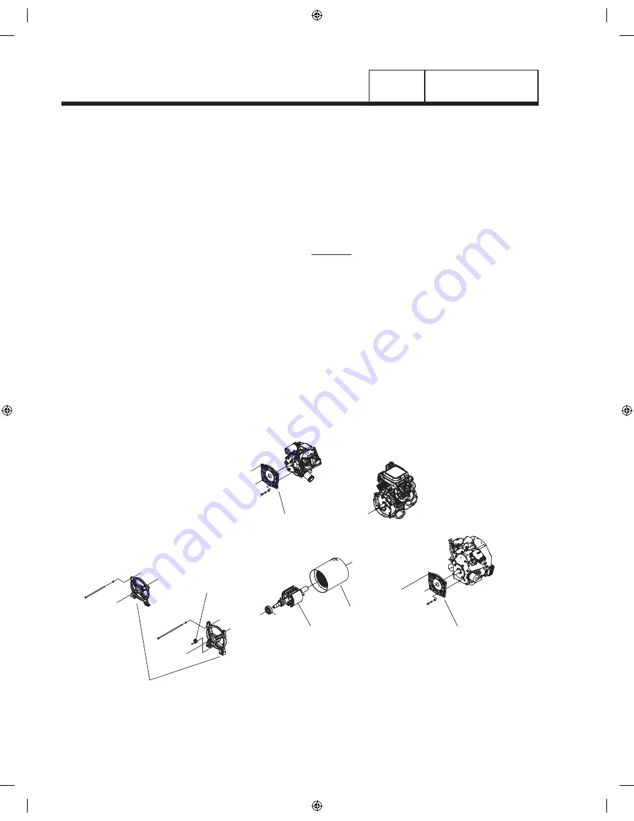
Figure 1 shows the major components of the AC
generator.
rotor aSSemBly
12-20 kW:
The 2-pole rotor must be operated at 3600 rpm to
supply a 60 Hertz AC frequency. The term “2-pole”
means the rotor has a single north magnetic pole and
a single south magnetic pole. As the rotor rotates, its
lines of magnetic flux cut across the stator assem-
bly windings and a voltage is induced into the stator
windings. The rotor shaft mounts a positive (+) and
a negative (-) slip ring, with the positive (+) slip ring
nearest the rear bearing carrier. The rotor bearing is
pressed onto the end of the rotor shaft. The tapered
rotor shaft is mounted to a tapered crankshaft and is
held in place with a single through bolt.
Figure 1. AC Generator Exploded View
Part 2
Page 32
AC GENERATORS
sEctioN 2.1
DEscriPtioN & comPoNENts
0G9266revA.indd 32
10/15/2008 11:27:08 AM


