Connecting the mixer systems
1-5
Revision J2005-2
J-Type
41617
&RQQHFWLQJ
#
WR
#
D
#60
SKDVH
#
RXWOHW
Connection to a 3-phase outlet is required on sites where the system voltage
between any one of the phases and neutral is 100-127V and the voltage between
any two of the phases is 200-240V. Before connecting to any 3-phase outlet, please
refer to a qualified electrician who understands your particular installation and the
local safety and wiring regulations. Under no circumstances should the 8019 and
8020 switch-mode power supply units be operated without the green/yellow safety
earth conductor connected to the building safety earth conductor system. Each
power unit is equipped with an input supply filter whose reference ground conductor
is the chassis. Failure to connect the green/yellow safety earth conductor to the cor-
rect earth/ground building reference is a safety and fire hazard.
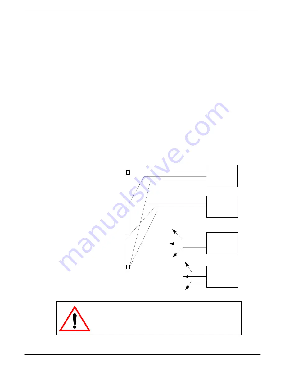
1.
Connect the LIVE (Brown) conductor on the “system 1” 8019 unit to the phase 1
(L1, RED) terminal on the 3-phase power outlet connector.
2.
Connect the NEUTRAL (Blue) conductor on the “system 1” 8019 unit and the
LIVE (Brown) conductor on the “system 1” 8020 unit to the Phase 2 (L2, YEL-
LOW) terminal on the 3-phase power outlet connector.
3.
Connect the NEUTRAL (Blue) conductor on the “system 1” 8020 unit to the
Phase 3 (L3, BLUE) terminal on the 3-phase power outlet connector.
4.
Connect the EARTH (Yellow/Green) conductor on the “system 1” 8019 unit and
the EARTH (Yellow/Green) conductor on the “system1 “8020 unit to the SAFETY
EARTH (Yellow/Green) terminal on the 3-phase power outlet connector.
5.
Repeat 1-4 for the “system 2” power units.
/LYH
1HXWUDO
(DUWK
/LYH
1HXWUDO
(DUWK
/LYH
1HXWUDO
(DUWK
/LYH
1HXWUDO
(DUWK
;34<
;353
;34<
;353
3+$6(
#4#+
/
4/#
5('
,
3+$6(
#5#+
/
5/#
<(//2:
,
3+$6(
#6#+
/
6/#
%/8(
,
/
4
/
5
6$)(7<
#
($57+
/
4
/
5
6$)(7<
#
($57+
6$)(7<
#
($57+
<(//2:
2
*5((1
NOTE: Connection between two phases in a 3-phase outlet should under no
circumstances be carried out where the single-phase voltage (the voltage
between one of the phases and neutral) exceeds 127V. The installation
should be carried out by a qualified electrician who understands your partic-
ular installation and the local safety and wiring regulations.
FIG 1-5. Connecting to a 3-phase outlet
(100-127V/200-240 system voltages)
Summary of Contents for J-Type
Page 1: ...Audio Mixing Console 056 6 10 n 95 4 1 07 g8 2...
Page 4: ...iv Table of contents J Type Revision J2005 2...
Page 6: ...vi General Precautions Revision J2005 2 J Type...
Page 8: ...viii Introduction J Type Revision J2005 2...
Page 72: ...3 22 7496 Dual Input Channel J Type Revision J2005 2...
Page 86: ...3 36 7830 Dual input channel J Type Revision J2005 2...
Page 96: ...4 10 7925 Programmable Group Module J Type Revision J2005 2...
Page 102: ...4 16 7972 Programmable Aux Groups Module J Type Revision J2005 2...
Page 110: ...4 24 7548 Programmable Routing Slave Mod Mk II J Type Revision J2005 2...
Page 146: ...6 14 7106 Quad Panning module J Type Revision J2005 2...
Page 154: ...7 8 6910 Oscillator PFL Stereo Aux module J Type Revision J2005 2...
Page 188: ...8 16 7956 DC Master Motor fader J Type Revision J2005 2...
Page 200: ...INDEX 4 J Type Revision J2005 2 W Wiring the switches 1 6 X XLR connections APP I...


