27
14. INSTALLATION INSTRUCTIONS
Installation must be made in accordance with the CSA B.365 « Installation code for solid-fuel-burning appliances and
equipment » standard in Canada and NFPA 90B « Standard for the installation of warm air heating and air conditioning
system » in the United States. Moreover, for all electrical connection, the Canadian standard CSA C22.1 « Canadian
electrical code » and in the United-States NFPA 70 standard « National Electrical Code » must be followed.
All controls and adjustments must be performed by a qualified technician. The blower speed must conform to the
recommendations of the Warm Air Heating and Air Conditioning National Association and should respect the static
pressure ranges in the warm air plenum of the furnace
We recommend that our woodburning hearth products be installed and serviced by professionals who are certified in
the United States by NFI (National Fireplace Institute®) or in Canada by WETT (Wood Energy Technical Training) or in
Quebec by APC (Association des Professionnels du Chauffage).
Inspect the furnace to make sure that nothing has been damaged in the shipping. Pull out the wiring kit and the
instructions manual from the firebox of the furnace and the accessories from the flue pipe.
The following section contains installation instructions for the caddy wood only, caddy wood / electric and caddy add-
on parallel configurations.
14.1. BLOWER INSTALLATION
To use the wood only configuration, the blower assembly (PA08567 – sold separately) is required. The installation
instructions are provided with the blower.
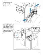
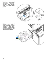
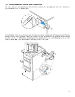
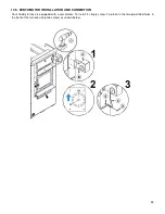
14.2. LINK BOARD INSTALLATION AND CONNECTION
The following installation instructions are identical whether the furnace controls are located on the left or on the right of
the furnace. The most accessible side is preferred to facilitate the connection of auxiliary heating sources or for
servicing.
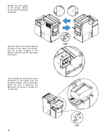
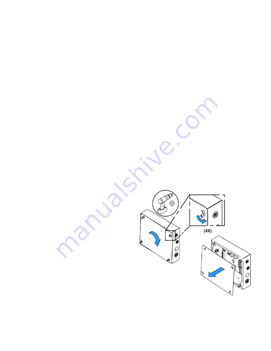
The components to be installed are in the combustion chamber of the furnace.
Remove the link board housing cover.
Summary of Contents for PF01015
Page 10: ...10 ADD ON WOOD ONLY WOOD ELECTRIC WOOD OIL ...
Page 13: ...13 INSTALLATION AND OPERATION INSTRUCTIONS CADDY ADD ON SERIAL INSTALLATION PF01015 ...
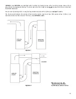
Page 16: ...16 Option 3 Option 4 ...
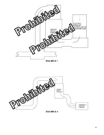
Page 17: ...17 EXAMPLE 1 EXAMPLE 2 ...
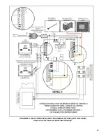
Page 63: ...63 20 GENERAL ELECTRICAL DIAGRAM STANDALONE FURNACE ...
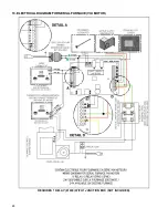
Page 64: ...64 21 ELECTRICAL DIAGRAM FOR PARALLEL FURNACE ...
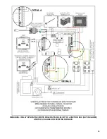
Page 65: ...65 22 ELECTRICAL DIAGRAM FOR ELECTRIC UNIT ...
Page 78: ...78 31 ELECTRICAL DIAGRAM BECKETT OIL UNIT ...
Page 79: ...79 32 ELECTRICAL DIAGRAM RIELLO OIL UNIT ...
Page 81: ...81 33 4 AIR CONDITIONNING DAMPER 33 5 HUMIDIFIER 33 6 HEAT PUMP ...
Page 82: ...82 34 EXPLODED VIEW AND PART LIST ...
Page 83: ...83 ...
Page 84: ...84 ...
Page 85: ...85 ...
Page 86: ...86 ...
Page 87: ...87 ...
Page 88: ...88 ...
Page 89: ...89 ...


