43
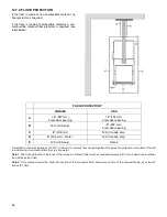
MODEL OUTPUT
(CFM)
TEMP. VAR.
(OF)
BTU/H TOTAL AMPERAGE
BREAKER ALIMENT.
CALIBRE
VOLTAGE
1 PHASE
# OF ÉLÉMENTS
15 kW
950
1,300
50
36
51195
75
100
4
120/240
3 – 5 kW
18 kW
950
1,300
60
44
61434
87
125
4
120/240
2 – 5 kW,
2 – 4 kW
20 kW
950
1,300
67
49
68260
95
125
3
120/240
4 – 5 kW
WOOD
15
120
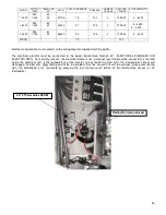
Electrical connections must conform to the wiring diagram supplied with the option.
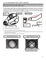
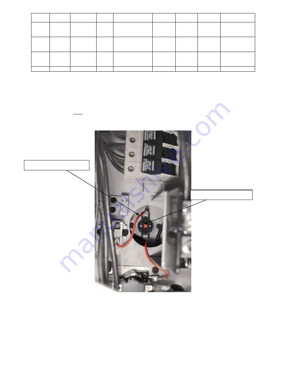
The electrical element must be connected to the power board (See Section 22 - ELECTRICAL DIAGRAM FOR
ELECTRIC UNIT). For security reasons, the electrical element has a manual reset thermostatic sensor that is located
inside the electrical unit. If the temperature of the electric unit exceeds the high limit, the thermostatic sensor will
disengage the elements. After finding and fixing the problem that has caused the unit to overheat (static pressure too
high, fan breakdown, etc.), reactivate by pressing the red “manual reset” button on the thermostatic sensor (L-170
thermodisc).
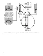
L-170 Thermodisc RESET
Red button manual reset
Summary of Contents for PF01015
Page 10: ...10 ADD ON WOOD ONLY WOOD ELECTRIC WOOD OIL ...
Page 13: ...13 INSTALLATION AND OPERATION INSTRUCTIONS CADDY ADD ON SERIAL INSTALLATION PF01015 ...
Page 16: ...16 Option 3 Option 4 ...
Page 17: ...17 EXAMPLE 1 EXAMPLE 2 ...
Page 63: ...63 20 GENERAL ELECTRICAL DIAGRAM STANDALONE FURNACE ...
Page 64: ...64 21 ELECTRICAL DIAGRAM FOR PARALLEL FURNACE ...
Page 65: ...65 22 ELECTRICAL DIAGRAM FOR ELECTRIC UNIT ...
Page 78: ...78 31 ELECTRICAL DIAGRAM BECKETT OIL UNIT ...
Page 79: ...79 32 ELECTRICAL DIAGRAM RIELLO OIL UNIT ...
Page 81: ...81 33 4 AIR CONDITIONNING DAMPER 33 5 HUMIDIFIER 33 6 HEAT PUMP ...
Page 82: ...82 34 EXPLODED VIEW AND PART LIST ...
Page 83: ...83 ...
Page 84: ...84 ...
Page 85: ...85 ...
Page 86: ...86 ...
Page 87: ...87 ...
Page 88: ...88 ...
Page 89: ...89 ...

