69
26. BURNER PUMP
When the tank is located below the unit, the basic single course pump, powered by a single duct, can
compensate for a drop of 8 feet (244 cm) measured between tank outlet and the height of entry into the
burner.
When the rise is more than 8 feet (244 cm) and not exceeding 10 feet (305 cm), a by-pass plug (provided
with the burner) must be inserted in the pump and an oil return pipe must be installed.
For more details,
see “INSTALLATION INFORMATIONS”, Part No. 21844 on the burner pump.
If the rise is higher than 10 feet (305 cm), a two stage pump may be required along with an oil return pipe.
27. APPLIANCE INSTALLATION
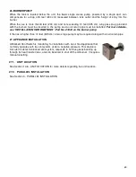
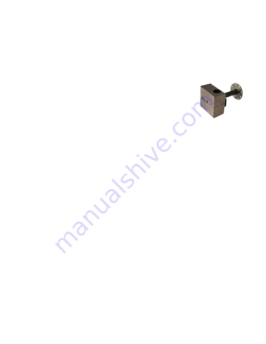
A Blocked Vent Switch is mandatory for installation with an oil fired appliance that
normally operates with its vent system under a negative pressure. This device is
intended to detect a blocked vent system, responds to hot flue gases backing up
through its heat transfer tube, and can be wired to shut off the oil burner. It requires
manual resetting.
27.1. UNIT LOCATION
See Section 14.6 - UNIT LOCATION for more details regarding the unit location.
27.2. PARALLEL INSTALLATION
See Section 0 - PARALLEL INSTALLATION
Summary of Contents for PF01015
Page 10: ...10 ADD ON WOOD ONLY WOOD ELECTRIC WOOD OIL ...
Page 13: ...13 INSTALLATION AND OPERATION INSTRUCTIONS CADDY ADD ON SERIAL INSTALLATION PF01015 ...
Page 16: ...16 Option 3 Option 4 ...
Page 17: ...17 EXAMPLE 1 EXAMPLE 2 ...
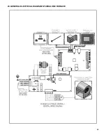
Page 63: ...63 20 GENERAL ELECTRICAL DIAGRAM STANDALONE FURNACE ...
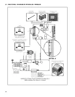
Page 64: ...64 21 ELECTRICAL DIAGRAM FOR PARALLEL FURNACE ...
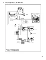
Page 65: ...65 22 ELECTRICAL DIAGRAM FOR ELECTRIC UNIT ...
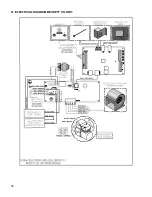
Page 78: ...78 31 ELECTRICAL DIAGRAM BECKETT OIL UNIT ...
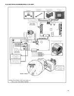
Page 79: ...79 32 ELECTRICAL DIAGRAM RIELLO OIL UNIT ...
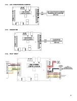
Page 81: ...81 33 4 AIR CONDITIONNING DAMPER 33 5 HUMIDIFIER 33 6 HEAT PUMP ...
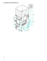
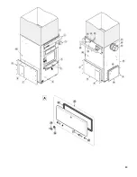
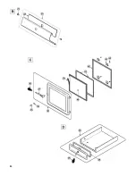
Page 82: ...82 34 EXPLODED VIEW AND PART LIST ...
Page 83: ...83 ...
Page 84: ...84 ...
Page 85: ...85 ...
Page 86: ...86 ...
Page 87: ...87 ...
Page 88: ...88 ...
Page 89: ...89 ...

