background image

17

EASY - SWEET

3

EN

11.5 

SWEET SIDE PANEL DISASSEMBLY 


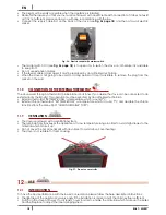
For this model there is NO need to remove the frame to disassemble the side panels.

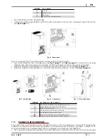
To access the internal stove parts, disassemble the side panels as indicated below:

• 

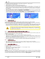
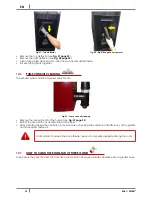
Loosen the 3 back screws (see 

Fig. 21 page 17

).

• 

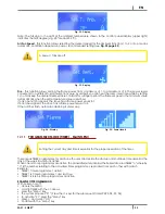
Turn the side panel outwards (see 

Fig. 22 page 17

).

• 

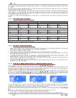
Disengage the front teeth and remove the side panel (see 

Fig. 23 page 17

).

• 

To assemble proceed in reverse order.

Fig. 21 - Loosen screws

Fig. 22 - Rotate side panels

Fig. 23 - Remove side panels

11.6 

SWEET FRAME DISASSEMBLY 


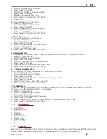
Proceed as follows to disassemble the frame:

Fig. 24 - Remove screws

Fig. 25 - Unhook frame

• 

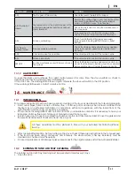
Remove the 2 screws at the bottom of the frame (see 

Fig. 24 page 17

).

• 

Unhook the frame by pushing it upwards and remove it (see 

Fig. 25 page 17

).

• 

To assemble proceed in reverse order.

11.7 

ELECTRIC CONNECTION 


Warning: the appliance must be installed by an authorized technician!

• 

The electric connection occurs through a cable with plug put in an electric socket which is able to support 

charge and tension specific of every model, as described in the technical datas table (see 

 page 36

).

Summary of Contents for EASY-SWEET 3

Page 1: ... 2016 CADEL srl All rights reserved tutti i diritti riservati en PELLET STOVE installation use and maintenance manual EASY SWEET3 ...

Page 2: ... MAIN MENU 23 12 12 PROGRAMMING EXAMPLES 24 12 13 NOTES FOR TIMER OPERATION 24 12 14 AUTO ECO MODE SEE SECTION F G SETTINGS MENU PAGE 20 24 12 15 SLEEP FUNCTION MAIN MENU 25 12 16 PELLETS RECIPE SEE SECTION J 25 12 17 SMOKE RPM VARIATION SEE SECTION I SETTINGS MENU PAGE 20 25 12 18 CHIMNEY SWEEP FUNCTION FOR MAINTENANCE TECHNICIANS ONLY SEE SECTION K SETTINGS MENU PAGE 20 25 12 19 STOVE CALIBRATIO...

Page 3: ...ension Dir 2004 108 EC for Electromagnetic compatibility Read carefully the instruction contained in this manual to obtain the best efficiency This instruction manual is an integral part of the product make sure it is delivered with the appliance also in case of sold to others In case of loss please ask a copy to your local Technical Assistance Service In Italy biomass system installation below 35...

Page 4: ...h the fume exhaust pipe and nor with every other part of the stove The user or whoever is operating the product must read and fully understand the contents of this installation and use guide before performing any operation Errors or incorrect settings can cause hazardous conditions and or poor operation The type of fuel to use is only the pellets Do not use the appliance as waste inceneretor Do no...

Page 5: ...use and maintenance manual are observed and therefore the product is used correctly The replacement of the entire system or the repair of one of its components does not extend the guarantee period and the original expiry date remains unchanged The guarantee covers the replacement or free repair of parts recognised as being faulty at source due to manufacturing defects To benefit from the guarantee...

Page 6: ...ry At the end of its working life the product must not be disposed of as urban waste It must be taken to a special differentiated waste collection centre set up by the local authorities or to a retailer that provides this service Separating and recycling prevents potential negative effects on the environment and health often caused by inappropriately disposing of product parts It also allows mater...

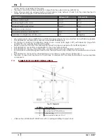
Page 7: ...tained with a perfect efficiency The chimney flue must be sole see Fig 1 page 7 with insulated stainless steel pipes 1 or installed on the existing chimney flue 2 Both this solutions must be endowed with an inspection plug 3 and or an inspection door 4 9 3 TECHNICAL FEATURES Fig 2 Inclined roof LEGEND Fig 2 page 7 1 Height over the ridge of the roof 0 5 mt 2 Roof inclination 10 3 90 4 Measured dis...

Page 8: ...materials in compliance with current regulations The flue system must be placed on the roof The chimney flue must be provided CE in accordance with EN 1443 regulation Please find attached an example of label Fig 3 Example of label 9 4 HEIGHT DEPRESSION The depression draught of a chimney flue depends also on its height Check the depression with the values provided at page 36 Minimum height 3 5 met...

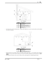
Page 9: ...he reflux area caused by the roof structure or by obstacles laying nearby see Fig 2 page 7 9 7 CHIMNEY COMPONENTS Fig 5 Chimney components LEGEND Fig 5 page 9 1 Chimney pot 2 Fume outlet 3 Chimney flue 4 Termal insulation 5 External wall 6 Chimney union 7 Fume pipe 8 Heat generator 9 Inspection door 10 T union with inspection plug 9 8 EXTERNAL AIR INLET Fig 6 Direct air inflow ...

Page 10: ...er If the stove is endowed with a sealed chamber and you want also the whole installation with sealed chamber please read the following instructions It is necessary to extract the air for combustion directly from outside Use a tube with minimum Ø60 mm and maximum 2 meters lenght to connect see the back of the stove French standards require installation in double walled flues concentric system The ...

Page 11: ... of a horizontal exhaust flue wall HO 2 6 mt see Fig 11 page 11 Fig 9 Flexible tube Fig 10 Connections Fig 11 Flue connections LEGEND Fig 10 page 11 Fig 11 page 11 I Combustion air intake with a diameter of 40 mm N Rubber fitting with a diameter of 40 60 mm R Flexible aluminium tube Q Coaxial pipe air combustion connection Y Coaxial pipe air combustion intake HO Height of coaxial flue with wall ho...

Page 12: ... direction it is obligatory always to use a union with angle 90 with inspection plug which enables an easy periodic cleaning of the pipes Please assure you that after the cleaning the inspection plugs are sealed with its efficient gasket It is forbidden to connect more appliances to the same fume conduit It is forbidden to convey in the same fume conduit exhausts from overhanging cooker hoods It i...

Page 13: ... external door which enables the chimney cleaning Fig 14 Example 3 LEGEND Fig 14 page 13 1 Insulating material 2 Inspection plug 3 Minimum safety distance 0 5 mt External chimney flue entirely made up of insulated stainless steel pipes i e with double wall of minimum Ø100 120 mm all must be firmly attached to the wall For chimney against wind effects please see Fig 4 page 8 Ducting system through ...

Page 14: ...uality materials such as stainless steel steel cast iron etc These materials before being sold on the market are tested in laboratory but despite this on the components which enable the pellets flow auger there could exist minimum differences in the material used in roughness and porosity which could generate usual variations in fuel transportation pellets causing a flame raising or drapping with ...

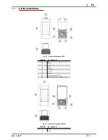
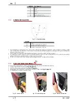
Page 15: ...Fig 15 General dimensions EASY LEGEND Fig 15 page 15 1 44 cm 2 92 cm 3 49 cm 4 21 cm 5 19 3 cm 6 11 5 cm 7 16 5 cm 8 Exhaust fumes d 8 cm 9 Hole combustion air inlet d 6 cm Fig 16 General dimensions SWEET3 LEGEND Fig 16 page 15 1 47 cm 2 94 cm ...

Page 16: ...f heat in the room see If the walls are made up of flammable materials check the safety distances see At maximum power check that the wall temperature does not ever exceed 80 C If it would be necessary please install a fire resistant plate on the concerned walls In some countries also masonring load bearing walls are considered flammable 11 4 EASY SIDE PANEL DISASSEMBLY To access the internal stov...

Page 17: ... Fig 22 Rotate side panels Fig 23 Remove side panels 11 6 SWEET FRAME DISASSEMBLY Proceed as follows to disassemble the frame Fig 24 Remove screws Fig 25 Unhook frame Remove the 2 screws at the bottom of the frame see Fig 24 page 17 Unhook the frame by pushing it upwards and remove it see Fig 25 page 17 To assemble proceed in reverse order 11 7 ELECTRIC CONNECTION Warning the appliance must be ins...

Page 18: ...re the stove can be connected to an external room thermostat This operation must be executed by an authorized technician External thermostat SET TEMP ROOM a temperature which is round 7 C External chronothermostat SET TEMP ROOM a temperature which is round 7 C and desable the chrono functions from the menu 03 01 CHRONO ENABLE OFF 11 9 VENTILATION The stove is endowed with a ventilation system The ...

Page 19: ...PLAY Menu items Fig 28 Display Fig 29 Display LEGEND Fig 28 page 19 Fig 29 page 19 1 Boiler lighting shutdown ESC 2 Scrolling of programming menu to decrease 3 Menu 4 Scrolling of programming menu to increase 5 Decrease set temperature programming functions 6 Increase set temperature programming functions 7 Display 8 Time 9 Status 10 Temperature set by user 11 Instant power 12 Ambient temperature ...

Page 20: ...witched off act as follows Press the menu button Scroll to Settings using the arrows Press menu to confirm Scroll to Cleaning using the arrows Press menu to confirm Select On with the keys Press menu to confirm and esc to exit c Screw Loading To select Screw loading only when the boiler is switched off act as follows Press the menu button Scroll to Settings using the arrows Press menu to confirm S...

Page 21: ...elect the test to be performed with the keys Press menu to confirm and esc to exit k Chimney Sweep Function To activate the Chimney Sweep Function function act as follows Press the menu button Scroll to Settings using the arrows Press menu to confirm Scroll to the Chimney Sweep Function function using the arrows Press menu to confirm Select On with the keys Off by default Press menu to confirm and...

Page 22: ...moke is present If after some months the flame appears weak and or orange colored or the glass tends to blackens and the burning pot to become encrusted clean the stove clean the fume conduit and the chimney flue 12 8 SWITCH OFF ON PANEL OFF WITH FLASHING FLAME If the shutdown key is pressed or if there is an alarm signal the boiler goes into the thermal shutdown phase which entails the automatic ...

Page 23: ...e power equal to 1 If 5 notches appear the stove has a flame power equal to 5 If the notches flash automatic cleaning is under way Fig 34 Display Fig 35 Power levels 12 11 PROGRAMMED MODE TIMER MAIN MENU Setting the current day and time is essential for the proper operation of the timer There are six TIMER programmes for each one the user can decide the start up and shutdown time as well as the da...

Page 24: ...ny effect while OFF will switch it off In the boiler on and timer active condition press the OFF key and the boiler will switch off it will switch on automatically at the next time set on the timer In the boiler off and timer active condition press the ON key and the boiler will switch on it will switch off at the time set on the active timer 12 14 AUTO ECO MODE SEE SECTION F G SETTINGS MENU PAGE ...

Page 25: ...ase with respect to the default setting 10 10 increase with respect to the default setting 15 15 increase with respect to the default setting 12 17 SMOKE RPM VARIATION SEE SECTION I SETTINGS MENU PAGE 20 If the installation presents difficulties for smoke evacuation no draught or no pressure in the duct the smoke and ash expulsion speed can be increased This change resolves all the potential probl...

Page 26: ... opening of the pellets bag It is necessary to avoid to fill the hopper with the pellet when the stove is running Do not get the bag of pellet in contact with hot stove surfaces Do not empty the hopper with remaining fuels unburnt pellet from the burning pot coming from ignition waster 12 21 PELLET REFUELLING TIMER This stove is equipped with a safety timer that activates after the pellet hopper d...

Page 27: ...rmful for the environment they must therefore be disposed of separately in the special containers Fig 46 Remote control LEGEND Fig 46 page 27 Button 1 Increase the desired temperature Button 2 Decrease the desired temperature Button 3 On off Button 4 Menu Button 5 Decrease the power level from 5 to 1 Button 6 Increase the power level from 1 to 5 13 SAFETY DEVICES AND ALARMS 13 1 SAFETY DEVICES The...

Page 28: ...evelops the boiler will go into alarm condition 13 10 BLACKOUT WITH THE BOILER ON In the event of a power cut BLACKOUT the boiler behaves as follows Blackout below 10 it returns to its operation in progress In the event of a power cut that lasts over 10 with the boiler on or in the start up stage when the boiler is powered again it goes back to the previous operating condition with the following p...

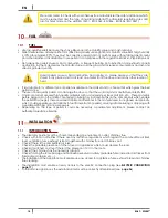
Page 29: ...to determine whether the warning cause is still present If this is the case the warning will be shown again otherwise the stove will switch to the OFF position If the warning is still present contact a service centre 14 MAINTEINANCE 14 1 INTRODUCTION For a long working life of the stove have a periodic cleaning of the stove as described in the following paragrafs Fume outlet pipes fume conduit chi...

Page 30: ... see Fig 51 page 30 The ash remains must be poured in a metal container with a sealed lid and this container must never get in touch with combustible materials for example put on a wooden floor as the inner ash keeps the embers firing for a long time Only when the embers are off the ash coul be poured in the organic waste Pay attention if the flame becomes red colured if it is weak or if black smo...

Page 31: ...2 fume chamber closing zincate panel screw which stands on under the door see Fig 53 page 31 Clean with a vacuum cleaner the ash which has accumulated on the inner see Fig 54 page 31 After the cleaning the opposite operation is to repeat checking the gasket efficiency and integrity if necessary provide for its replacement by an Authorized Technician 14 5 FUME PASSAGES CLEANING Clean the fume passa...

Page 32: ...very month Fig 59 Fume conduit cleaning Remove the inspection lid of the T union see Fig 59 page 32 Extract the ash which has accumulated in the inner After cleaning repeat the operation in reverse order checking the condition and efficiency of the gasket and if necessary replace it It is important to sealed the cap othrwise noxiuous fumes will propagate among the room 14 7 HOW TO CLEAN THE ROOM F...

Page 33: ... steel wools muriatic acid or other corrosive and abrasive materials 14 10 CLEANING OF PAINTED METAL PANELS To clean painted metal panels use a soft cloth Do not use degreasant agents like alcool diluents acetone gasoline because these could irremediably damage the varnish 14 11 GASKET REPLACEMENT In case of deterioration of fire door hopper or fume chamber gaskets it is necessary to replace them ...

Page 34: ...onnected Burned protection fuse in the electric socket Replace the protection fuses in the electric socket 3 15A 250V Faulty control display Replace the control display Faulty flat cable Replace the flat cable Faulty electronic board Replace the mother board Pellets do not reach the combustion chamber Empty hopper Full the hopper Open fire door or open pellet door Close fire door and pellet door a...

Page 35: ...ove Provide immediately at the inner cleaning of the stove The fume fan is out of order The pellets can burn also thanks to chimney flue depression without the aid of the fume fan Have the fume fan immediately replaced It can be noxious to health to let the stove running without fume fan The exchanger fan continues to turn even though the stove has just cooled Faulty fume temperature probe Replace...

Page 36: ...e stove extract the fuses to change with the aid of a screwdriver for opening the shutter see Fig 61 page 36 Fig 61 Shutter with fuses to remove Proceed as follows Remove the sides see the dedicated chapters After these operations you can have access at the following components geared motor ignition plug ambient fan fume fan ambient probe fume probe thermostat electronic board pressostat For clean...

Page 37: ...3 123 50 mg Nm3 Medium POWDER CONTENTS at 13 O2 Max 7 mg Nm3 7 mg Nm3 CHIMNEY DEPRESSION Max 12 Pa 11 Pa MINIMUM SAFETY DISTANCE from flammable materials 30 cm 30 cm ON SHARED CHIMNEY FLUE NO NO FUME OUTLET DIAMETER Ø80 mm Ø80 mm COMBUSTIBLE Pellet Ø6 7 mm Pellet Ø6 7 mm PELLETS HEATING VALUE 5 kWh kg 5 kWh kg PELLETS HUMIDITY 10 10 HEATING VOLUME 18 20 C Coeff 0 045 kW Min Max 57 6 156 m3 57 6 15...

Page 38: ...NOTE ...

Page 39: ...NOTE ...

Page 40: ...oves wood cooking stoves thermostoves pellet fireplace inserts CADEL srl FREEPOINT by Cadel Via Foresto Sud 7 31025 Santa Lucia di Piave TV ITALY tel 39 0438 738669 fax 39 0438 73343 www cadelsrl com Partner of Rev 00 2016 ...

Reviews: