IDRO PRINCE
3
12-16-23-23 H
2
O - IDRO PRINCE 30-30 H
2
O - AQUOS
3
16-23-23 H
2
O - IDRON 16-22 AIRTIGHT - MIRA 16-22 - TESIS 16-23 AIRTIGHT - HIDROFIRE 22.8
15
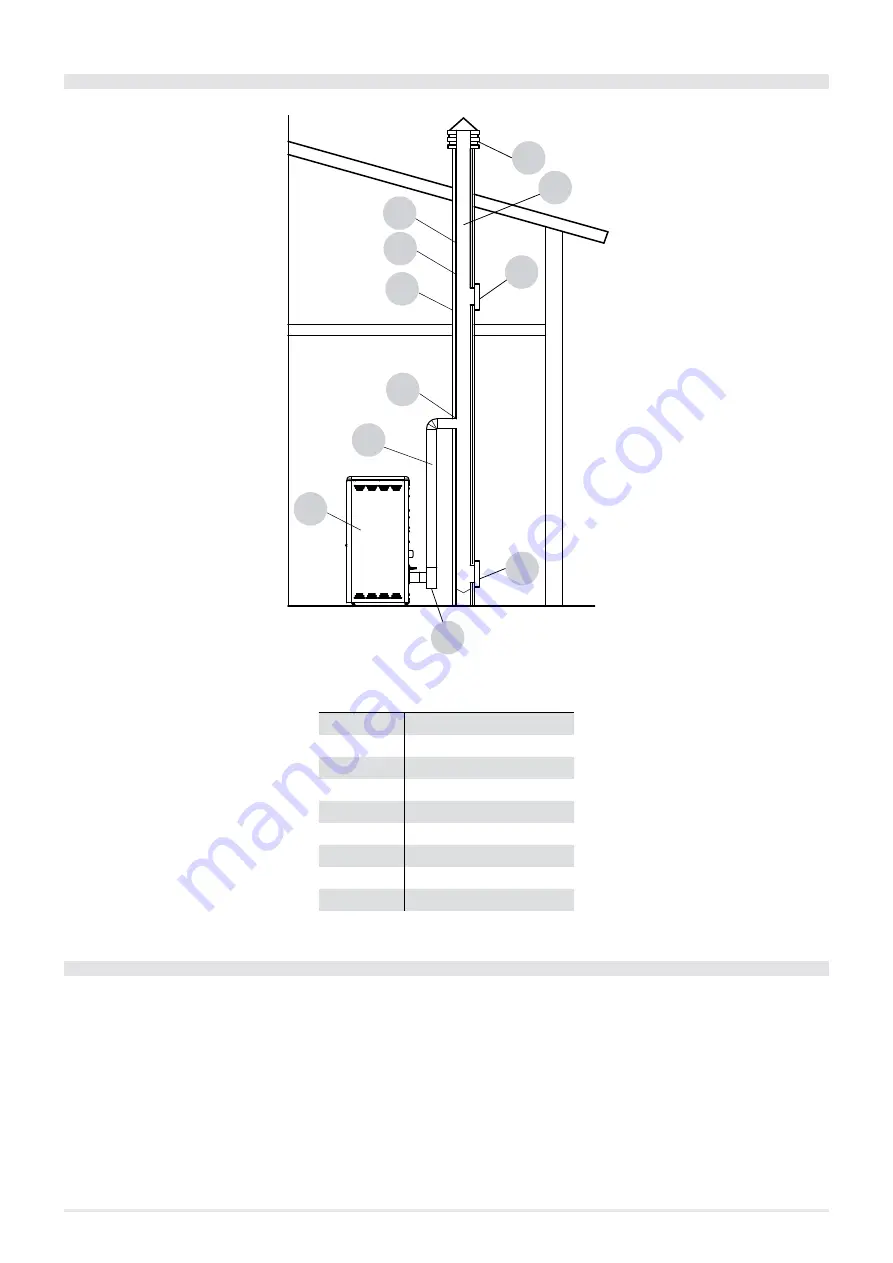
3.11 CHIMNEY COMPONENTS
1
9
9
2
3
4
5
6
7
8
9
Fig. 10 - Chimney components
LEGEND
1
Chimney cap
2
Backflow duct
3
Smoke duct
4
Thermal insulation
5
External wall
6
Chimney fitting
7
Smoke channel
8
Heat generator
9
Inspection door
3.12 OUTSIDE AIR VENT
It is mandatory to create an adequate outside air vent that supplies the combustion air necessary for the product to work properly. The
flow of air between the outside and the installation room can be direct, via an opening on an external wall of the room (see “Solution
1”
); or indirect, by drawing air from rooms that are adjacent and permanently communicating with the room in which the pro-
duct is installed (see “Solution 2”
). Adjacent rooms do not include bedrooms, bathrooms, garages, and rooms at risk for fire in
general. During installation, you must check the minimum distances necessary to be able to draw air from the outside. Consider doors
and windows that could interfere with proper air flow to the stove (see the diagram below).
The air vent must have an 80cm
2
minimum total net surface: said surface must be increased accordingly if there are other active gene-
rators in the room (for example, electric fan to extract foul air, range hood, other stoves, etc.) that can create a vacuum in the room. With
all the appliances switched on, make sure the pressure loss between the room and the outside does not exceed 4 Pa (even for airtight
appliances if the combustion air has not been appropriately ducted to the outside). If necessary, increase the air vent intake cross-sec-
tion, which must be done near the floor and always protected by an external bird guard grate and such not to be clogged by any objects.


