IDRO PRINCE
3
12-16-23-23 H
2
O - IDRO PRINCE 30-30 H
2
O - AQUOS
3
16-23-23 H
2
O - IDRON 16-22 AIRTIGHT - MIRA 16-22 - TESIS 16-23 AIRTIGHT - HIDROFIRE 22.8
54
9
5
8
6
7
12
3
12
2
7
10
8
11
5
1
4
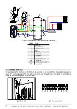
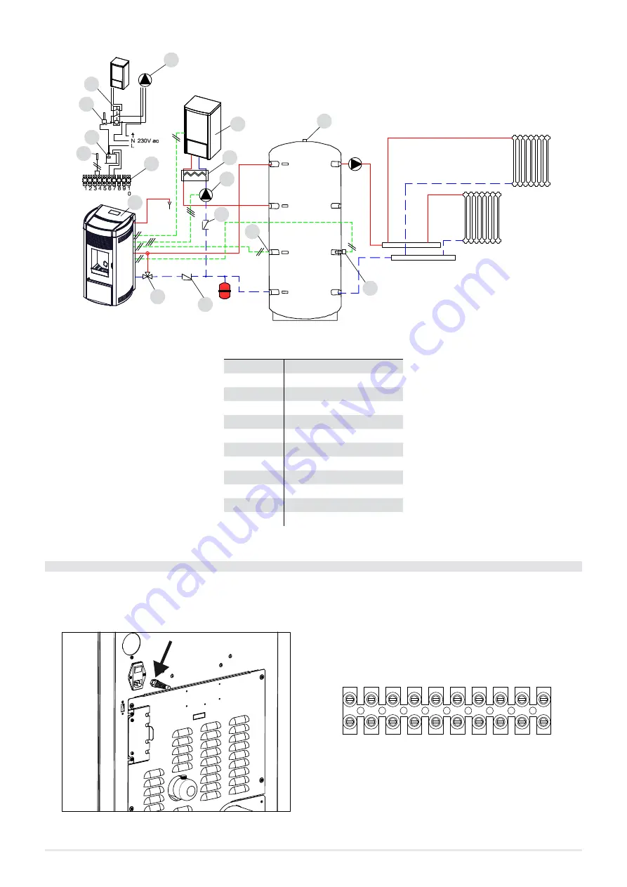
Fig. 56 - System with: pellet stove, puffer, and auxiliary boiler (wall mounted)
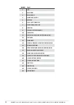
LEGEND
1
Pellet Boiler
2
Rear terminal board
3
Anti-condensate valve
4
Puffer
5
Puffer Probe
6
Auxiliary boiler
7
Plate exchanger
8
System pump
9
Auxiliary boiler thermostat
10
Activation relay
11
Aux boiler connection module
12
Non-return valve
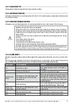
11.14 OPERATING MODE
The operating mode for hydro boilers is AUTOMATIC only (manual mode is not envisioned). Flame modulation is managed accor-
ding to the “System configuration” of the room probe placed on the rear of the appliance (see drawing), by the external thermo-
stat, by the boiler water temperature or by the NTC probes.
1 2 3 4 5 6 7 8 9 10
Fig. 57 - Probe position
Fig. 58 - 10-pole terminal board


