background image

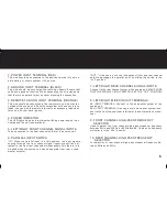
TROUBLE SHOOTING GUIDE

12

SYMPTOM

1. No power.

2. “Motorboating”: the unit power indica-

    tor going off repeatedly when the audio

    system is on.

3. The unit heats up quickly even when the

    audio system is at moderate volume.

4. When the engine is running the audio system

    has a whining noise that remains unchanged

    or disappears with the increase of audio

    volume.

5. When the engine is running, the audio system

    has a whining noise that increases or decreases

    with the volume of all sources (radio, CD, or MP3).

6. When the engine is running, the audio system has 

    has a whining noise that increases or decreases

    with the CD/MP3 mode ONLY.

7. Obvious distortion at low volume.

8. Over all sound effect good, but bass is abnormal

    (more bass at the two extreme settings of the

    balance control that at the center setting).

PROBABLE CAUSE

• Check all the ground, B+ and remote terminals for tight connection.

• Check all fuses.

• Use a volt/ohm meter to check all power wire connected to see if the system

   is rec12V.

• Check if the unit B+ power input is connected to directly 

   to a +12V power source.

• Check the battery voltage. If low, recharge or replace it.

• Check if the unit has a good ground connection.

• Check all ground connections.

• Check for speaker short.  

• Check all power wires and ensure that they are connected to a +12V power source.

• Check all ground connections.

• Check if the source unit and the mobile electronic crossover are grounded at the same reference point.  

• Install a 10 amp in-line filter on the red power wire of the unit. 

• If whining persists, check the alternator diodes and the voltage regulator.

• This is commonly known as “radiated” noise. It is not caused by the unit and thus is beyond the scope of

   this manual. Please contact your local retailer/installer for assistance.

• Output level of various channels not compatible, refer to FINAL SYSTEM CHECK on the previous page.

• The subwoofers are “out-of-phase” with each other thus cancelling the bass when the balance control is

   at the center position. Check the wiring from the amplifier to the subwoofers (positive [+] and negative [-]

   to negative [-]).

Summary of Contents for CXR-7

Page 1: ...3 WAY ELECTRONIC CROSSOVER OWNERS MANUAL CXR 7 ...

Page 2: ......

Page 3: ...CONTENTS Specifications 3 Features 4 Controls Indicators and Terminal 5 8 Installation 9 10 Final System Check 11 Troubleshooting Guide 12 2 ...

Page 4: ...High Pass Subwoofer Boost Input Impedance Output Impedance Output Gain Output Voltage Level Dimensions 14 4 Volts DC negative Ground 0 5 Amp Max 0 01 THD 1 Volt Output Level 10Hz 30Hz 3dB 95dB 60dB 25 400Hz 500 8000Hz 25 400Hz 25 400Hz 18dB per Octave 3rd Order Butter Worth 12dB per Octave 3rd Order Butter Worth Single Octave 0dB to 12dB Variable at 45Hz 20K Ohms 100 Ohms 1 2 6dB 7 Volts Max 5 5 W...

Page 5: ...se For a source unit having a single pair of signal outputs an adapter is needed to split the source signal for the front and rear inputs With the mobile electronic crossover by engaging the parallel input feature an external adapter is no longer necessary This power supply design provides constant voltage to the cross over regardless of the battery s voltage to ensure consistent out put performan...

Page 6: ...CONTROLS INDICATORS and TERMINALS 5 CXR 7 ...

Page 7: ...con nect to the front channel input terminal of the next electronic cross over Connect to the rear channel output of the source unit MAKE SURE THAT THE PARALLEL INPUT SWITCH IS AT THE OUT POSITION Used to select the front channel high pass crossover frequency between 25Hz and 400Hz or 500Hz and 8K Hz when its frequency multiplier is in the x20 position For selection of rear channel high pass cross...

Page 8: ...ont channel high pass from 25Hz 400Hz to 500Hz 8K Hz Connect to the front channel amplifier left right inputs Used to adjust the rear channel output signal level Connect to the rear channel amplifier left right inputs Used to adjust the subwoofer channel output signal level Connect to the subwoofer channel amplifier left right inputs Allows you to set the low pass crossover frequency for the sub w...

Page 9: ...AMPLIFIER WIRING DIAGRAMS 8 Four Channel bi amp system stereo front rear Two Channel tri amp system CXR 7 CXR 7 ...

Page 10: ...t mixed in out as output Another compatible electronic crossover Front inputs Left right front outputs Front amplifier Left right inputs Left right rear outputs Rear amplifier Left right inputs Left right subwoofer outputs Subwoofer amplifier Left right inputs Power input terminal b Battery Positive terminal Ground input terminal gnd Vehicle chassis Bare metal spot Remote turn on input terminal So...

Page 11: ...ELECTRICAL WIRING DIAGRAM 10 Electrical wiring diagram CXR 7 ...

Page 12: ...rossover and the other audio components permanently please conduct the following noise check 1 Start the engine and turn on source unit 2 Rev the engine and vary the audio volume to check for radiated engine noise If there is an alternator whining noise or tic tic noise refer to the trouble shooting guide on the next page If the problem persists consult your local retailer installer for assistance...

Page 13: ...r wire connected to see if the system is receiving 12V Check if the unit B power input is connected to directly to a 12V power source Check the battery voltage If low recharge or replace it Check if the unit has a good ground connection Check all ground connections Check for speaker short Check all power wires and ensure that they are connected to a 12V power source Check all ground connections Ch...

Page 14: ...ecifications subject to change and or improvement without notice Though we tried our best to ensure that this manual is free and clear of errors please don t hold us responsible for printing errors www cadencesound com ...

Reviews: