background image

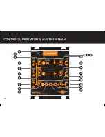
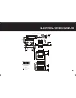
CONTROLS, INDICATORS, and TERMINALS

7

11. FRONT CHANNEL HIGH-PASS FREQUENCY

      MULTIPLIER

17. LEFT/RIGHT FRONT CHANNEL OUTPUT 

      TERMINALS

18. REAR CHANNEL OUTPUT LEVEL CONTROL

19. LEFT/RIGHT REAR CHANNEL OUTPUT TERMINALS

20. SUBWOOFER OUTPUT LEVEL CONTROL

21. LEFT/RIGHT SUBWOOFER OUTPUT TERMINALS

22. SUBWOOFER OUTPUT LEVEL REMOTE CONTROL

      TERMINAL     

12. SUBWOOFER FREQUENCY SELECTOR

13. BASS SHAPER BOOST SWITCH

14. PHASE INVERTER

15. SUBWOOFER STEREO/MONO SWITCH

16. FRONT CHANNEL OUTPUT LEVEL CONTROL

Positioning  this  switch  at  the  “x20”  position  changes  the  range 

of  selectable  crossover  frequency  for  the  front  channel  high-pass 

from 25Hz - 400Hz to 500Hz - 8K Hz.

Connect to the front channel amplifier left/right inputs.

Used to adjust the rear channel output signal level.

Connect to the rear channel amplifier left/right inputs.

Used to adjust the subwoofer channel output signal level.

Connect to the subwoofer channel amplifier left/right inputs

Allows  you  to  set  the  low-pass  crossover  frequency  for  the  sub-

woofer channel between 25Hz and 400Hz.

When activated this circuit provides a single octave boost of 12dB 

at 45Hz to equalize the woofer enclosure.

Placing the switch at the “180” position shifts the subwoofer out-

put’s signal 180

°

 out of phase relative to the front and rear output 

signals.

For selection of stereo or mono mode subwoofer output.

For adjusting the front channel output signal level.

Summary of Contents for CXR-7

Page 1: ...3 WAY ELECTRONIC CROSSOVER OWNERS MANUAL CXR 7 ...

Page 2: ......

Page 3: ...CONTENTS Specifications 3 Features 4 Controls Indicators and Terminal 5 8 Installation 9 10 Final System Check 11 Troubleshooting Guide 12 2 ...

Page 4: ...High Pass Subwoofer Boost Input Impedance Output Impedance Output Gain Output Voltage Level Dimensions 14 4 Volts DC negative Ground 0 5 Amp Max 0 01 THD 1 Volt Output Level 10Hz 30Hz 3dB 95dB 60dB 25 400Hz 500 8000Hz 25 400Hz 25 400Hz 18dB per Octave 3rd Order Butter Worth 12dB per Octave 3rd Order Butter Worth Single Octave 0dB to 12dB Variable at 45Hz 20K Ohms 100 Ohms 1 2 6dB 7 Volts Max 5 5 W...

Page 5: ...se For a source unit having a single pair of signal outputs an adapter is needed to split the source signal for the front and rear inputs With the mobile electronic crossover by engaging the parallel input feature an external adapter is no longer necessary This power supply design provides constant voltage to the cross over regardless of the battery s voltage to ensure consistent out put performan...

Page 6: ...CONTROLS INDICATORS and TERMINALS 5 CXR 7 ...

Page 7: ...con nect to the front channel input terminal of the next electronic cross over Connect to the rear channel output of the source unit MAKE SURE THAT THE PARALLEL INPUT SWITCH IS AT THE OUT POSITION Used to select the front channel high pass crossover frequency between 25Hz and 400Hz or 500Hz and 8K Hz when its frequency multiplier is in the x20 position For selection of rear channel high pass cross...

Page 8: ...ont channel high pass from 25Hz 400Hz to 500Hz 8K Hz Connect to the front channel amplifier left right inputs Used to adjust the rear channel output signal level Connect to the rear channel amplifier left right inputs Used to adjust the subwoofer channel output signal level Connect to the subwoofer channel amplifier left right inputs Allows you to set the low pass crossover frequency for the sub w...

Page 9: ...AMPLIFIER WIRING DIAGRAMS 8 Four Channel bi amp system stereo front rear Two Channel tri amp system CXR 7 CXR 7 ...

Page 10: ...t mixed in out as output Another compatible electronic crossover Front inputs Left right front outputs Front amplifier Left right inputs Left right rear outputs Rear amplifier Left right inputs Left right subwoofer outputs Subwoofer amplifier Left right inputs Power input terminal b Battery Positive terminal Ground input terminal gnd Vehicle chassis Bare metal spot Remote turn on input terminal So...

Page 11: ...ELECTRICAL WIRING DIAGRAM 10 Electrical wiring diagram CXR 7 ...

Page 12: ...rossover and the other audio components permanently please conduct the following noise check 1 Start the engine and turn on source unit 2 Rev the engine and vary the audio volume to check for radiated engine noise If there is an alternator whining noise or tic tic noise refer to the trouble shooting guide on the next page If the problem persists consult your local retailer installer for assistance...

Page 13: ...r wire connected to see if the system is receiving 12V Check if the unit B power input is connected to directly to a 12V power source Check the battery voltage If low recharge or replace it Check if the unit has a good ground connection Check all ground connections Check for speaker short Check all power wires and ensure that they are connected to a 12V power source Check all ground connections Ch...

Page 14: ...ecifications subject to change and or improvement without notice Though we tried our best to ensure that this manual is free and clear of errors please don t hold us responsible for printing errors www cadencesound com ...

Reviews: