background image

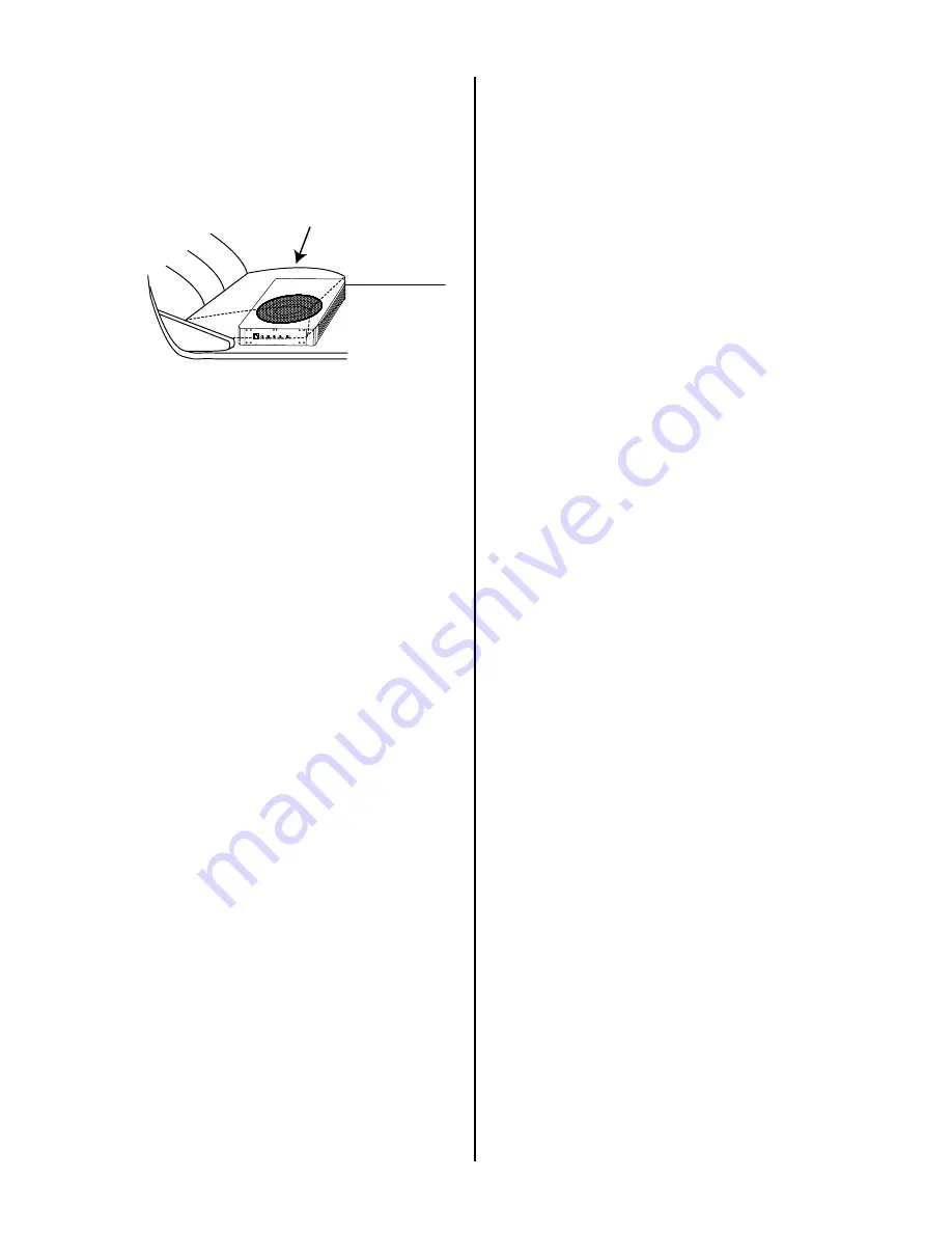
1. Find a suitable location in the vehicle

in which to mount the amplifier.

A typical location is shown below:


2. Make sure there is sufficient air

circulation around the inteded

mounting location.

3. Mark the location for the mounting

hole screws by positioning the cabinet

where you wish to install it. Make a

small mark to identify the position and

remove the unit.

Thoroughly clean the area you plan to

attach the subwoofer, using a vacuum

cleaner.

4

Mounting the subwoofer

Connecting the subwoofer

Vehicle seat

REMOTE

LEVEL

 BASS 
BOOST

LPF

PHASE

  SUB
SONIC

POWER(GREEN)
PROTECT(RED)

Before doing any wiring, look through

this manual and identify the diagrams

to follow for power, input and speaker

connections for your particular

installation. Be sure you understand

all the connections before you proceed.

1. Connect the ground terminal to the

closest point on the chassis of the

vehicle. Keep this ground wire to less

than 39" (100cm) in length. Use 8

gauge (or heavier) wire.

2. Connect the remote terminal to the

remote output of the head unit using

16 gauge (or heavier) wire.

3. Connect an empty fuse holder within

18" (45cm) of the car battery, and run

8 gauge (or heavier) cable from this

fuse to the amplifier location.

4. Check that the fuse holder is empty.

Then connect the fuse holder to the

"BATT+" connection on the amplifier.

Summary of Contents for QSA-8.2

Page 1: ...User s Manual 8 Super Compact Bass Enclosure With 2 Channel Amplifier Output Sa 8 2 ...

Page 2: ...el control connection Power Connections Output High Level Input Wiring 10 9 11 Troubleshooting 10 Specifications Congratulations on your purchase of a CADENCE amplified subwoofer It has been designed engineered and manufactured to bring you the highest level of performance and quality and will afford you years of listening pleasure Thank you for making CADENCE your choice for car audio entertainme...

Page 3: ...oofer level with the remote level control module Features Your new Amplified subwoofer features the following MOSFET PWM Pulse Width Modulated Power Supply Thermal overload and speaker short protection Soft turn on circuit Remote turn on turn off circuit Variable input gain control Variable low and high pass crossovers Variable bass boost 0 to 18dB Variable phase shift 0 or 180 degree RCA low leve...

Page 4: ...ect these conditions before attempting to power up the subwoofer again Protection circuitry General precautions SHOCK HAZARD Do not open the case of this product There are dangerous voltages present within the unit There are no user serviceable parts within the unit installing and using your new amplified subwoofer please become familiar with all the information contained in this manual Please kee...

Page 5: ...POWER GREEN PROTECT RED Before doing any wiring look through this manual and identify the diagrams to follow for power input and speaker connections for your particular installation Be sure you understand all the connections before you proceed 1 Connect the ground terminal to the closest point on the chassis of the vehicle Keep this ground wire to less than 39 100cm in length Use 8 gauge or heavie...

Page 6: ...set the volume control on the head unit to about 3 4 volume and adjust the subwoofer s input level controls to just below the level of distortion 10 Further fine tuning of the various controls may be necessary to obtain best results Do not mistake the input level control for a volume control It is designed ONLY to match the output level of your audio source to the input level of your subwoofer Do ...

Page 7: ...TER 7 The LOW P ASS rotary potentiometer permits the setting of the low pass filter value PHASE SHIFT Use this switch to help compensate for time alignment problems in the system Such problems usually result from having the subwoofer at a different distance from the listener than the other speakers in the system 8 AUTO POWER ON 10 s i F F O N O N O R E W O P O T U A e h T for high level speaker le...

Page 8: ... use a fuse with a different value and NEVER replace the fuse with a wire or coin 3 4 1 2 OUTPUT HI LEVEL INPUT The output high level terminal permits for high level signal in It also allows for the amplified signal to be sent to your system speakers left part OUTPUT for a true 2 1 system If you are using the RCA inputs low level you must disconnect the high level plug on the cable beam in order t...

Page 9: ...t connect BOTH the high level and low level inputs from your receiver to your amplifier at the same time T OUTPUT High Level Input Wiring he high level input s should only be used when your receiver lacks RCA outputs If the RCA outputs are not present connect the speaker outputs from the receiver to the high level input connector of the amplifier Be sure to observe polarity to avoid audio phase pr...

Page 10: ...e change speaker phase as per option B GREY BLACK R GREY R WHITE BLACK L WHITE L R Purple R Purple BLACK L Green L Green BLACK Chassis ground point Battery FUSE NOTE In this connection the AUTO TURN ON switch is in the OFF position If you use high level inputs AUTO TURN ON switch should be in the ON position The unit will automatically turn on when there is signal input If the unit detects no sign...

Page 11: ...se ratio Frequency response Input sensitivity high level Input sensitivity low level Low Pass Filter Bass Boost Subsonic Filter Subwoofer 8inch 30A 344 x 250 x 68 Fuse rating Dimensions L x W x H mm 100W 2Ohm 0 4 90dB 20Hz 150Hz 0 8V 180mV 50Hz 150Hz 0 to 18dB MODEL QSA8 2 2x75W 4Ohm 0 1 100dB 50Hz 20KHz 1 0V 200mV SUB STEREO Specifications Load 20Hz 50Hz 50Hz 150Hz HPF 2 Ohm 4 8 Ohm 8 SUPER COMPA...

Page 12: ...ontrol settings High hiss in the sound Disconnect all RCA inputs to the power sub s control panel If the hiss disappears then plug in the component driving the amplifier and unplug its inputs If the hiss disappears at this point go on until the faulty noisy component is found It is best to set the amplifier s input level control as low as possible The best subjective signal to noise ratio is achie...

Reviews: