
INSTALLATION INSTRUCTIONS
STRAIN RELIEF
CONNECTOR
KNOCK-OUT
(TWIST TO REMOVE)
SUPPLY WIRE
GROUNDING
SCREW
¾"
(1.9cm)
Min.
¾"
(1.9cm)
Min.
PARED
ADY
ACENT
E
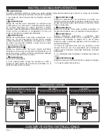
1.
WARNING
Verify that the electrical supply wires are the same voltage
as the heater.
2. If replacing an existing heater, check the label of the old
heater for voltage and wattage information.
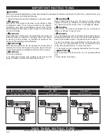
3. All electrical work and materials must comply with the
National Electric Code (NEC), the Occupational Safety and
Health Act (OSHA), and all state and local codes.
4. If you need to install a new circuit or need additional wir-
ing information, consult a qualified electrician.
5. Use copper conductors only.
6.
WARNING
Risk of Electrical Shock. DO NOT install the heater direct-
ly above bathtub or sink. DO NOT install in shower stall
area (Manufacturer recommends a minimum 2 foot (61 cm)
clearance).
7. Heater must be installed in a wall can:
Model CE
Wall Can CC
8.
WARNING
Risk of Fire. DO NOT install the heater in a floor, in the ceil
-
ing, below a towel bar, behind a door, or anywhere the air
discharge may be blocked in any manner.
9.
WARNING
Fire or Explosion May Occur. A heater has hot and arcing or
sparking parts inside. Do not use it in areas where gasoline,
paint, or flammable vapors or liquids are used or stored.
10.
WARNING
Risk of Electrical Shock. Connect grounding lead to ground-
ing screw provided. Keep all foreign objects out of heater.
11.
WARNING
Risk of Fire. This heater is hot when in use. Caution—High
Temperature. Risk of Fire. Keep electrical cords, drapery,
furnishings, and other combustibles at least 3 feet (0.9 m)
from the front of the heater and 6 inches (15.2 cm) above
and on both sides.
__________________________
Part One
__________________________
REPLACEMENT: If you are replacing an existing Com-Pak model,
proceed to Part Two, page 5
. Confirm that your existing wall can is
mounted flush with outside of sheetrock. Adjust if necessary.
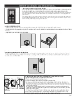
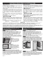
PLACEMENT: Install vertically. Heater is not approved for horizontal or ceiling mount applications. ADA requirements are met if the
heater is installed between 12½ inches (31.8 cm) and 42 inches (1.1 m) from the floor. The recommended height is 24 inches (61 cm)
from the floor to the bottom of the wall can (See Figure 4).
CONTROLS: A built-in digital thermostat is included. May not be used with a wall thermostat.
REQUIRED MINIMUM distance of ¾ inches (1.9 cm) from adja
-
cent surfaces, such as walls, and 4½ inches (11.4 cm) from the
floor (See Figure 4). Cadet recommends 24 inches (61 cm) from
floor for optimum performance. Heaters must be spaced at least 3
feet (0.9 m) apart.
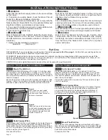
Secure the wall can to the stud with 2 screws (not included). (See
Figures 1 and 2). As an option, the rubber shim provided may be
attached to side of wall can to square the wall can to the stud.
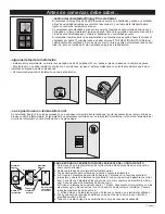
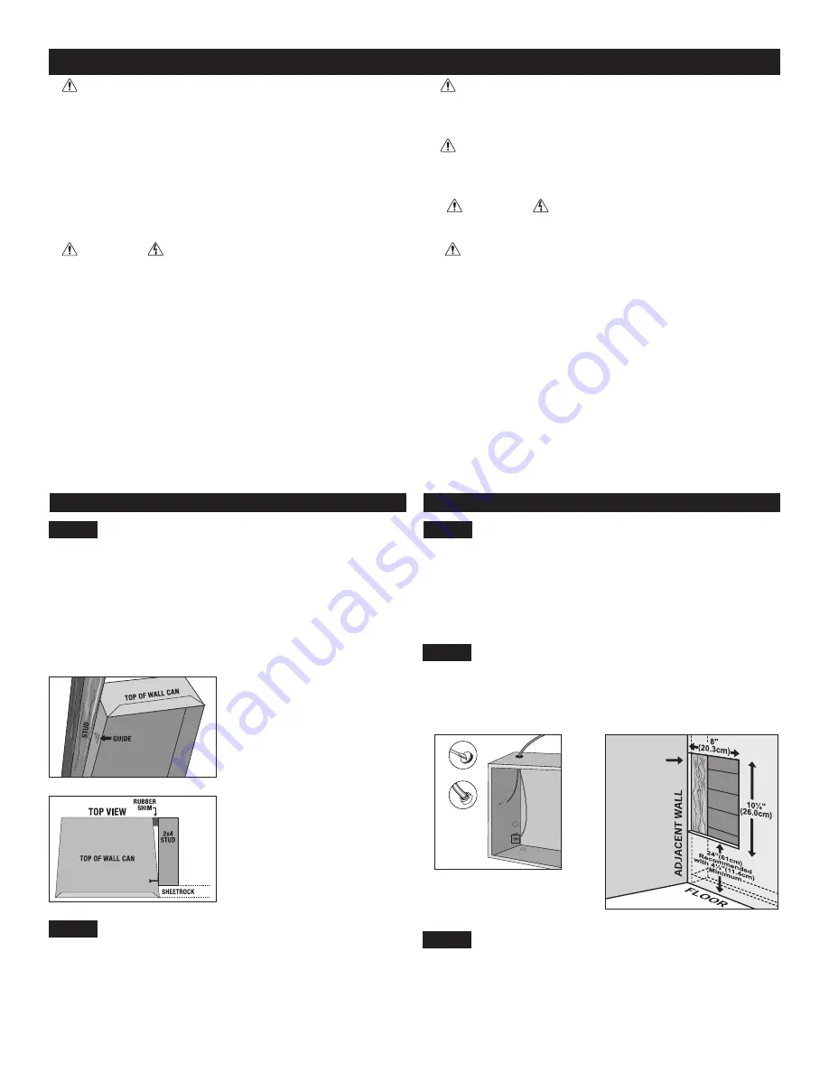
STEP 1
Mount The Wall Can
Figure 1
Figure 2
Face of wall can must extend
½ inch (1.3 cm)
or ⅝ inch (1.6
cm) from face of stud to allow for
thickness of sheetrock.
Attach wall can to stud with screws
(not included) through holes provid-
ed in wall can. IMPORTANT: wall
can should be mounted flush with
outside of sheetrock.
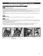
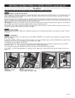
STEP 2
Route Supply Wires
Route supply wire from the circuit breaker to the heater. Remove
a knockout from the wall can and attach the supply wire with a
strain relief connector (not included) leaving a minimum of 6 inch-
es (15.2 cm) wire lead. Connect supply ground wire to grounding
screw in wall can (See Figure 3).
Proceed to Part Two.
STEP 1
Cut A Hole In The Wall
REQUIRED MINIMUM distance of ¾ inches (1.9 cm) from
adjacent surfaces, such as walls, and 4½ inches (11.4 cm) from
the floor (See Figure 4). Cadet recommends 24 inches (61 cm)
from floor for optimum performance. Heaters must be spaced at
least 3 feet (0.9 m) apart.
Cut a hole 8 inches (20.3 cm) wide by 10¼ inches (26 cm) high
next to a wall stud.
STEP 2
STEP 3
Route Supply Wires
Mount The Wall Can
Insert wall can into opening; keeping wall can flush with wall sur
-
face. Secure can to wall stud with 2 screws (not included)
through
holes provided in can. IMPORTANT: wall can should be mounted
flush with ouside of sheetrock.
Proceed to Part Two.
Route supply wire from the circuit breaker to the heater. Remove
a knockout from the wall can and attach the supply wire with
a strain relief connector (not included) leaving a minimum of
6 inches (15.2 cm) wire lead. Connect supply ground wire to
grounding screw in wall can (See Figure 3).
Figure 3
Figure 4
How do I install for new construction?
How do I install in an existing wall?
Page 4


