background image

EN / 10

4.2 Bilgisayarın kurulması

Tarayıcı yazılımı en az Windows 10 veya daha yeni bir sürüm gerektirir. Tüm sürücülerin güncel olduğundan emin olun (grafik kartı, USB, 

anakart, vb...). Tarayıcının sorunsuz çalışmasını sağlamak için önerilen asgari bilgisayar iş istasyonu gerekliliklerine uyun.

Bilgisayarın kullanım kılavuzuna bakın.

4.3 Yazılımın kurulması

Tarama yazılımı, tedarik edilen iş istasyonlarına önceden kurulmuştur. Kurulu değilse, yazılımı bayinizden temin edebilir veya müşteri 

hizmetlerimizin uzaktan kurmasını sağlayabilirsiniz. Bunu yapmak için CADstar Technology'nin müşteri hizmetleriyle iletişime geçin. Bkz. 

"Müşteri hizmetleri" bölümü.

Yazılımı lisanslamak için bir internet bağlantısının olması gerektiğini unutmayın. Bu, her yeni kurulum için yapılmalıdır.

Kurulum için yönetici hakları gereklidir.

Destek birimimiz "TeamViewer" ile çalışmaktadır. Lütfen bu yazılımı indirin (www.teamviewer.com). Kurulumdan 

sonra, destek birimimizin bilgisayarınıza bağlanabilmesi için lütfen kimliğinizi ve şifrenizi hazır bulundurun.

5. Çalışma süreci

Yazılımı başlattıktan sonra, Seçenekler menüsü altında tarayıcı kalibrasyonunu gerçekleştirmelisiniz. Bunu yapmak için, kalibrasyon plaka-

sını tarayıcıya yerleştirin ve kalibrasyonu başlatın.

Ana sayfa tarayıcı yazılımı    


Seçenekler > Tarayıcı kalibrasyonu 

VEYA Menü  


Seçenekler > Tarayıcı kalibrasyonu


Başarılı bir kalibrasyondan sonra yeni bir vaka oluşturabilirsiniz. Aşağıdaki alanlar zorunludur ve seçilmesi veya doldurulması gerekir:

• 

Hasta

• 

Doktor

• 

Model türü

• 

Tarama modu türü


Daha fazla ayrıntı için lütfen bkz. yazılım kullanım kılavuzu.

Tarama menüsündeyseniz tarayıcıda bulunan bir modeli tarayabilirsiniz.


5.1 Kimlik tanıma

Her aksesuar, tarayıcının halihazırda tarayıcıda ne bulunduğunu belirleyip uygun işlevleri gerçekleştirebildiği kendi kimlik tanıma özelliğine 

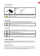
Açıktaki altın pimlere dikkat edin (24V). Bunlara kısa devre yaptırmayın!

5.2 LED gösterge çubuğu

LED çubuğu yazılımdaki durumları göstermek için kullanılır.

Beyaz titreşim > Yazılım bağlantısı yok

Kırmızı > Hata

Gökkuşağı > Kalibrasyon

Mavi ilerleme çubuğu > Tarama ilerleme göstergesi

5.3 Tarayıcının kapatılması

Tarayıcıyı kapatmak için Açma/Kapama düğmesine en az 1 saniye basın.

Tarayıcı başlamıyor

Tarayıcı açılırken yanmazsa güç kaynağını kontrol edin ve AC adaptörünün tarayıcıya bağlı olup olmadığını kontrol edin.

Destek birimimizle iletişime geçin

Tarayıcı bilgisayarda tanınmıyor

Azami uzunluğu 1.5 m olan kaliteli USB kabloları kullandığınızdan emin olun (CADstar'ın aktif USB uzatma kablolarının kullanıldığı 

durumlar hariç). Bir testi tamamlamak için kabloyu değiştirin

USB portunun USB3.0 özelliklerini karşıladığından emin olmak için kontrol edin

Güncel olduğundan emin olmak için aygıt yöneticisinde sürücü durumunu kontrol edin

Cihaz üzerindeki LED'lerin açık olup olmadığını kontrol edin 

Bilgisayarı ve tarayıcıyı yeniden başlatın

Destek birimimizle iletişime geçin

Tarama sonuçlarında çizgiler görünüyor

Tarama sırasında ışıktaki değişikliklere dikkat edin, çünkü bu çizgilenmeye neden olabilir. Bu durum genellikle tarama sırasında hare-

ket eden panjurlardan veya ağaçlar yahut pencerelerdeki yansımalar nedeniyle değişen güneş ışığından kaynaklanır. 

Örneğin neon tüpler veya LED aydınlatma gibi yayılabilen titrek ışık. Bunu kontrol etmek için akıllı telefonunuzla ağır çekim bir video 

kaydedebilirsiniz. Titrek ışık görünürse, nedenini araştırıp ortadan kaldırın.

Tarama sonuçlarında delikler görünüyor

 Deliği kapatmak üzere bu alan için "Integrate" aracını kullanın.

7. İşletmeci için temizlik ve bakım çalışmaları

Uzun ürün ömrü ve tarama doğruluğu sağlamak için cihazın düzenli olarak temizlenmesi ve kalibre edilmesi gerekir.

Summary of Contents for CS.Neo2

Page 1: ...www cadstar dental Instruction manual CS Neo2 CS Neo2 Pro CS Neo2 Max...

Page 2: ...Select a setup area 6 2 3 Carrying points 7 2 4 Installation example 7 3 Device overview and connections 8 3 1 Components of the scanner 8 3 2 Scanner connector strip 8 3 3 Power supply unit 9 3 4 USB...

Page 3: ...means of a risk assessment This chapter lists all residual risks and warnings from the risk assessment The information in this document is subject to change without notice Every effort has been made i...

Page 4: ...s and must absorb all vibrations The ambient light must be taken into account when setting up the device There must not be any change in the ambient light during the scan operation such as might occur...

Page 5: ...and damage the scanner The product is not an automatically functioning device it must be loaded manually Furthermore any liability and warranty claims are excluded in the event of non compliance with...

Page 6: ...s nal location Inspection and cleaning may only be carried out by technical specialists with product speci c training or under the guidance of the customer service department Operators Product trainin...

Page 7: ...owing Avoid rapidly changing lighting conditions such as moving shadows o ce lighting that ickers uorescent lamps LED Never expose the scanner to direct sunlight Avoid direct proximity to heat sources...

Page 8: ...on The open side of the scanner should face away from the body 2 4 Installation example The following gure is merely a schematic representation intended to provide an illustration of the overall syste...

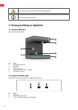
Page 9: ...scanner 2 1 4 5 6 3 No Description 1 Connector strip rear side 2 Swivel bracket 3 Housing 4 Optical scan unit 5 Model support CS Neo2 Max two support 6 On Off button 3 2 Scanner connector strip The co...

Page 10: ...affected Take care of the calibration plate so that the surface is not damaged 4 Function and installation This optical 3D scanner is designed for the dental eld to measure and digitize jaw models in...

Page 11: ...are This must be done for each new installation Administrator rights are required for the installation Our support works with TeamViewer Please download this software www teamviewer com After installa...

Page 12: ...Dstar are used Exchange the cable to complete a test Check to ensure the USB port meets the USB3 0 speci cation Check the driver status in the device manager to ensure it is up to date Check if the LE...

Page 13: ...our software manual Start the scanning process using software and proceed step by step according to the software instructions If anything is unclear contact our customer service department see chapte...

Page 14: ...S Neo2 CS Neo2 Pro CS Neo2 Max Mains voltage 90 264VAC 90 264VAC 90 264VAC Mains frequency 47 63Hz 47 63Hz 47 63Hz Power supply unit 90 Wh 90 Wh 90 Wh Scanner voltage 24V DC 10 24V DC 10 24V DC 10 Pow...

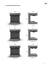
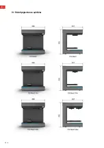
Page 15: ...EN 14 9 1 Product diagrams clearances...

Page 16: ...on of the use of certain hazardous substances in electrical and electronic equipment according to RoHS electronics 2011 65 EU Applicable standards Safety requirements DIN EN IEC62368 1 2022 09 EMC DIN...

Page 17: ...und aufstellen 6 2 2 Stellplatz w hlen 6 2 3 Tragepunkte 7 2 4 Aufstellbeispiel 7 3 Ger te bersicht und Anschl sse 8 3 1 Komponenten des Scanners 8 3 2 Scanner Anschlussleiste 8 3 3 Netzteil 9 3 4 USB...

Page 18: ...sind alle Restrisiken und Warnhinweise aus der Risikobeurteilung gelistet Die Informationen in diesem Dokument k nnen ohne Vorank ndigung ge ndert werden Bei der Erstellung dieses Dokumentes wurde jed...

Page 19: ...ellungsort muss das Umgebungslicht beachtet werden Es darf w hrend des Scanbetriebs zu keiner nderung des Umgebungslichts kommen wie es z B durch Schatten von B umen oder Jalousien auftr ten k nnte Au...

Page 20: ...immungsgem er Verwendung kann es zu Gef hrdungen von Personen und zu einer Besch digung des Scanners kommen Das Produkt ist kein selbst ndig funktionsf higes Ger t es muss manuell best ckt werden Dar...

Page 21: ...ektion und Reinigung d rfen nur durch technische Fachkr fte mit produktspezifischer Ausbildung oder unter Anleitung des Kundendienstes geschehen Bedienungspersonal Produkteinschulung Regelm ige Sicher...

Page 22: ...hselnde Lichtbedingungen wie z B bewegte Schatten B robeleuchtung die flimmern Leuchtstofflampen LED Setzen Sie den Scanner niemals direkter Sonneneinstrahlung aus Vermeiden Sie die direkte N he von W...

Page 23: ...Seite des Scanners sollte dabei vom K rper weg zeigen 2 4 Aufstellbeispiel Bei der folgenden Abbildung handelt es sich lediglich um eine schematische Darstellung welche eine Veranschaulichung des Gesa...

Page 24: ...2 1 4 5 6 3 Nr Beschreibung 1 Anschlussleiste R ckseite 2 Schwenkkonsole 3 Geh use 4 Optische Scaneinheit 5 Modellaufnahme CS Neo2 Max zwei Aufnahmen 6 Ein Austaster 3 2 Scanner Anschlussleiste Die An...

Page 25: ...n Sie auf die Kalibrationsplatte damit die Oberfl che nicht besch digt wird 4 Funktion und Installation Dieser Optische 3D Scanner ist f r den dentalen Bereich konzeptioniert um Kiefermodelle dreidime...

Page 26: ...ies muss bei jeder Neuinstallation vorgenommen werden F r die Installation sind Administratorenrechte erforderlich Unser Support arbeitet mit TeamViewer Bitte laden Sie sich diese Software herunter ww...

Page 27: ...e f r einen Test das Kabel berpr fen Sie den USB Port ob er die USB3 0 Spezifikation erf llt Kontrollieren Sie den Treiberstatus im Ger temanager auf Aktualit t Kontrollieren Sie ob die LEDs am Ger t...

Page 28: ...finden Sie in unserem Software Handbuch Starten Sie den Scan Vorgang mittels Software und gehen Sie Schritt f r Schritt laut Softwareanweisung vor Bei Unklarheiten kontaktieren Sie unseren Kundendiens...

Page 29: ...eo2 CS Neo2 Pro CS Neo2 Max Netzspannung 90 264VAC 90 264VAC 90 264VAC Netzfrequenz 47 63Hz 47 63Hz 47 63Hz Leistung Netzteil 90 Wh 90 Wh 90 Wh Scanner Spannung 24V DC 10 24V DC 10 24V DC 10 Leistungs...

Page 30: ...14 DE 9 1 Produktskizzen Abst nde...

Page 31: ...n of the use of certain hazardous substances in electrical and electronic equipment according to RoHS electronics 2011 65 EU Applicable standards Safety Requirements DIN EN IEC62368 1 2022 09 EMC DIN...

Page 32: ...unti di supporto 7 2 4 Esempio di installazione 7 3 Panoramica dell unit e collegamenti 8 3 1 Componenti dello scanner 8 3 2 Morsettiera dello scanner 8 3 3 Alimentatore 9 3 4 Cavi USB 9 3 5 Accessori...

Page 33: ...sidui che sono stati valutati mediante una valutazione dei rischi Questo capitolo elenca tutti i rischi residui e le avverten ze della valutazione dei rischi Le informazioni contenute in questo docume...

Page 34: ...nte l installazione dell apparecchio necessario tenere conto della luce ambientale Durante l operazione di scansione la luce ambientale non deve subire variazioni ad esempio a causa dell ombra di albe...

Page 35: ...ettere in pericolo le persone e di danneggiare lo scanner Il prodotto non un dispositivo funzionante in modo indipendente e deve essere caricato manualmente Inoltre in caso di non conformit all uso pr...

Page 36: ...osizionarla nella sua sede de nitiva L ispezione e la pulizia possono essere eseguite solo da tecnici specializzati con una formazione speci ca sul prodotto o sotto la guida del servizio clienti Opera...

Page 37: ...nti Evitare condizioni di luce che cambiano rapidamente come ombre in movimento illuminazione dell u cio che sfarfalla lampade uorescenti LED Non esporre mai lo scanner alla luce diretta del sole Evit...

Page 38: ...perto dello scanner deve essere rivolto verso il corpo 2 4 Esempio di installazione La gura seguente solo una rappresentazione schematica che ha lo scopo di fornire un illustrazione del sistema comple...

Page 39: ...er 2 1 4 5 6 3 N Descrizione 1 Morsettiera posteriore 2 Staffa girevole 3 Alloggiamento 4 Unit di scansione ottica 5 Supporto del modello CS Neo2 Max due supporti 6 Pulsante di accensione spegnimento...

Page 40: ...sabilit del prodotto potrebbero essere compromessi Fare attenzione alla piastra di calibrazione in modo da non danneggiarne la super cie 4 Funzione e installazione Questo scanner ottico 3D stato proge...

Page 41: ...eguita a ogni nuova installazione Per l installazione sono necessari i diritti di amministratore Il nostro supporto funziona con TeamViewer Scaricare questo software www teamviewer com Dopo l instal l...

Page 42: ...ttive di CADstar Sostituire il cavo per un test Controllare la porta USB per veri care se conforme alle speci che USB3 0 Controllare che lo stato del driver sia aggiornato nella Gestione periferiche C...

Page 43: ...ili nel manuale del software Avviare il processo di scansione con il software e procedere passo dopo passo seguendo le istruzioni del software Se qualcosa non chiaro contattare il nostro servizio clie...

Page 44: ...CS Neo2 Max Tensione di rete 90 264VAC 90 264VAC 90 264VAC Frequenza di rete 47 63Hz 47 63Hz 47 63Hz Uscita dell alimentatore 90 Wh 90 Wh 90 Wh Tensione dello scanner 24V DC 10 24V DC 10 24V DC 10 Fun...

Page 45: ...IT 14 9 1 Schizzi del prodotto e distanze...

Page 46: ...l uso di determinate sostanze pericolose nelle apparecchiature elettriche ed elettroni che secondo la direttiva RoHS 2011 65 UE Standard applicabili Requisiti di sicurezza DIN EN IEC62368 1 2022 09 EM...

Page 47: ...de instalaci n 7 3 Visi n general de la unidad y las conexiones 8 3 1 Componentes del esc ner 8 3 2 Regleta de conectores del esc ner 8 3 3 Fuente de alimentaci n 9 3 4 Cables USB 9 3 5 Accesorios 9 4...

Page 48: ...han evaluado mediante una valoraci n de riesgos Este cap tulo enumera todos los riesgos y advertencias residuales de la evaluaci n de riesgos La informaci n contenida en este documento est sujeta a c...

Page 49: ...nes t cnicas y debe ser capaz de absorber todas las vibraciones La luz ambiental debe tenerse en cuenta al instalar la unidad No debe haber cambios en la luz ambiental durante el escaneado como podr a...

Page 50: ...no se utiliza para los nes previstos podr a da arse y poner en peligro a las personas El producto no es un dispositivo de funcionamiento aut nomo debe cargarse manualmente Adem s en caso de incumplim...

Page 51: ...tiva La inspecci n y la limpieza solo pueden ser realizadas por especialistas t cnicos con formaci n espec ca sobre el producto o bajo la orientaci n del servicio de atenci n al cliente Operarios Form...

Page 52: ...ciones de iluminaci n que cambien r pidamente como sombras en movimiento iluminaci n parpadeante l mparas uorescentes LED No exponga nunca el esc ner a la luz solar directa Evite la proximidad directa...

Page 53: ...a La abertura del esc ner debe mirar en direcci n opuesta al cuerpo 2 4 Ejemplo de instalaci n La siguiente imagen solo es una representaci n esquem tica que pretende ofrecer una ilustraci n de todo e...

Page 54: ...N Descripci n 1 Regleta de conectores trasera 2 Soporte giratorio 3 Carcasa 4 Unidad de escaneado ptico 5 Entrada del modelo CS Neo2 Max dos entradas 6 Bot n de encendido apagado 3 2 Regleta de conect...

Page 55: ...afectadas las provisiones para garant as y los riesgos de responsabilidad por pro ductos defectuosos Tenga cuidado con la placa de calibraci n para no da ar la super cie 4 Funcionamiento e instalaci n...

Page 56: ...n a Internet para obtener la licencia del software Esto debe hacerse con cada nueva instalaci n Se requieren derechos de administrador para la instalaci n Nuestro equipo de asistencia trabaja con Tea...

Page 57: ...empresa CADstar Sustituya el cable para comprobar si funciona Compruebe si el puerto USB se ajusta a la especi caci n USB3 0 Compruebe el estado del controlador en el administrador de dispositivos par...

Page 58: ...siga paso a paso las instrucciones del mismo Si algo no est claro p ngase en contacto con nuestro servicio de atenci n al cliente ver cap tulo Servicio de atenci n al cliente Aseg rese de que los c r...

Page 59: ...ed 90 264 V CA 90 264 V CA 90 264 V CA Frecuencia de red 47 63 Hz 47 63 Hz 47 63 Hz Salida de la fuente de alimentaci n 90 Wh 90 Wh 90 Wh Tensi n del esc ner 24 V CC 10 24 V CC 10 24 V CC 10 Consumo d...

Page 60: ...14 ES 9 1 Bocetos y espaciado de los productos...

Page 61: ...ciones a la utilizaci n de determinadas sustancias peligrosas en aparatos el ctricos y electr nicos seg n la directiva RoHS 2011 65 EU Normas aplicables Requisitos de seguridad DIN EN IEC62368 1 2022...

Page 62: ...6 2 2 Choisir un emplacement 6 2 3 Points de portage 7 2 4 Exemple d installation 7 3 Aper u de l appareil et connexions 8 3 1 Composants du scanner 8 3 2 Panneau de connexion du scanner 8 3 3 Bloc d...

Page 63: ...es r siduels et les avertissements issus de l valuation des risques Les informations contenues dans ce document peuvent tre modi es sans pr avis Lors de la r daction de ce document tous les efforts po...

Page 64: ...en compte en ce qui concerne le lieu d installation Il ne doit pas y avoir de changement de la lumi re ambiante pendant le fonctionnement du scanner comme cela pourrait tre le cas avec l ombre d un a...

Page 65: ...ation peut mettre en danger les personnes et endommager le scanner Le produit n est pas un appareil qui fonctionne de mani re autonome il doit tre quip manuel lement En outre les droits de responsabil...

Page 66: ...nettoyage ne doivent tre effectu s que par du personnel technique sp cialis ayant re u une formation sp ci que au produit ou sous la direction du service apr s vente Personnel de service Formation au...

Page 67: ...changent rapidement comme les ombres en mouvement les clairages de bureau qui scintillent lampes uorescentes LED N exposez jamais le scanner la lumi re directe du soleil vitez la proximit directe de...

Page 68: ...ersonne Le c t ouvert du scanner doit alors tre orient l oppos du corps 2 4 Exemple d installation La gure suivante n est qu une repr sentation sch matique destin e illustrer l ensemble du syst me Vei...

Page 69: ...scription 1 Panneau de connexion arri re 2 Console pivotante 3 Bo tier 4 Unit de num risation optique 5 Enregistrement du mod le CS Neo2 Max deux enregistrements 6 Bouton marche arr t 3 2 Panneau de c...

Page 70: ...es risques de responsabilit du fait des produits pourraient tre in uenc s Faites attention la plaque de calibrage pour ne pas endommager la surface 4 Fonctionnement et installation Ce scanner optique...

Page 71: ...la licence du logiciel Ceci doit tre fait chaque nouvelle instal lation Les droits d administrateur sont n cessaires pour l installation Notre support travaille avec TeamViewer Veuillez t l charger ce...

Page 72: ...n test V ri ez que le port USB est conforme la sp ci cation USB3 0 Contr lez l tat des pilotes dans le gestionnaire de p riph riques pour voir s ils sont jour Contr lez si les LED de l appareil sont a...

Page 73: ...ctions sur le r talonnage de votre scanner dans notre manuel du logiciel D marrez le processus de num risation l aide du logiciel et proc dez tape par tape en suivant les instructions du logiciel En c...

Page 74: ...0 264VAC 90 264VAC 90 264VAC Fr quence du r seau 47 63Hz 47 63Hz 47 63Hz Puissance du bloc d alimentation 90 Wh 90 Wh 90 Wh Tension du scanner 24V DC 10 24V DC 10 24V DC 10 Puissance absorb e en fonct...

Page 75: ...FR 14 9 1 Sch mas de produits distances...

Page 76: ...on of the use of certain hazardous substances in electrical and electronic equipment according to RoHS electronics 2011 65 EU Applicable standards Safety Requirements DIN EN IEC62368 1 2022 09 EMC DIN...

Page 77: ...3 3 1 4 3 1 5 4 1 6 4 1 7 4 1 8 5 1 9 5 1 10 5 1 11 5 2 5 2 1 6 2 2 6 2 3 7 2 4 7 3 8 3 1 8 3 2 8 3 3 9 3 4 USB 9 3 5 9 4 9 4 1 9 4 2 10 4 3 10 5 10 5 1 11 5 2 11 5 3 11 6 11 7 11 7 1 12 7 2 12 7 3 1...

Page 78: ...2 RU 1 3D CADstar Technology 1 1 1 1 1 CADstar 1 1 2 3D...

Page 79: ...RU 3 1 2 CE 2014 30 2014 35 2011 65 1 3 CADstar Technology Link www cadstar dental CADstar Technology Grasslau 30 5500 Bischofshofen 1 4 1 4 1 1 4 2 3D...

Page 80: ...4 RU 1 4 3 CADstar Technology CADstar Technology 1 5 1500 x x 200 x 200 x 150 CADstar Technology CADstar Technology 1 6 1 7 5 C 35 C 31 C 20 80 35 C 20 50 500 3000...

Page 81: ...RU 5 1 8 1 9 1 10 1 11 3D 2...

Page 82: ...6 RU 2 1 2 2...

Page 83: ...RU 7 2 3 1 2 1 2 11 13 2 4 2cm 15cm 1 2 3D 3 4 5 6 7...

Page 84: ...8 RU 3 3 1 2 1 4 5 6 3 1 2 3 4 5 CS Neo2 Max 6 3 2 Master USB 3 0 USB 3 0 24V 1 24 2 USB C 3 0 3 USB C 3 0 CS Neo2 Max...

Page 85: ...RU 9 3 3 MEAN WELL GST90A 24 P1M 90 264 127 370 47 63 Power 90 24 3 75 A 3 4 USB USB USB C 5 1 4 1 4 USB 2 USB USB USB 3 5 4 3D 4 1 USB 24 USB CADstar USB USB USB 2 x 5 10...

Page 86: ...10 RU 4 2 Windows 10 USB 4 3 CADstar Technology TeamViewer www teamviewer com 5 Home Scan Software Patient Doctor Model type Scan mode type...

Page 87: ...RU 11 5 1 24 5 2 5 3 1 6 USB 1 5 USB CADstar USB USB3 0 7...

Page 88: ...12 RU 7 1 3D 7 2 7 3 3D CADstar Technology 8...

Page 89: ...35 C 18 C 35 C 15 C 50 C 15 C 50 C 15 C 50 C 0 3000 0 3000 0 3000 2 2 2 CS Neo2 CS Neo2 Pro CS Neo2 Max 90 264 90 264 90 264 47 63 47 63 47 63 90 90 90 24 10 24 10 24 10 35 35 45 1 1 1 2 x 6 4 x 6 2...

Page 90: ...14 RU 9 1...

Page 91: ...011 65 DIN EN IEC62368 1 2022 09 EMC DIN EN 55032 2022 08 DIN EN IEC 61000 3 2 2019 12 DIN EN IEC 61000 3 3 2020 07 DIN EN IEC 61000 4 2 2009 12 DIN EN IEC 61000 4 3 2021 11 DIN EN IEC 61000 4 4 2013...

Page 92: ...se poate prinde pentru mutare 7 2 4 Exemplu de instalare 7 3 Prezentare general a dispozitivului i conexiuni 8 3 1 Componentele scannerului 8 3 2 Reglet conectori scanner 8 3 3 Unitate de alimentare...

Page 93: ...siguran Acestea au fost calculate prin intermediul unei evalu ri a riscurilor Acest capitol enumer toate riscurile reziduale i avertiz rile rezultate din evaluarea riscurilor Informa iile din document...

Page 94: ...oarb toate vibra iile La montarea dispozitivului trebuie s se in cont de lumina ambiant Nu trebuie s apar nicio modi care a luminii ambiante pe durata ac iunii de scanare de exemplu modi c ri cauzate...

Page 95: ...pentru siguran a persoanelor i poate duce la deteriorarea scannerului Produsul nu este un dispozitiv cu func ionare automat trebuie nc rcat manual n plus n cazul nerespect rii utiliz rii vizate se exc...

Page 96: ...ia Activit ile de inspec ie i de cur enie pot realizate exclusiv de speciali ti tehnici care au instruire speci c produsului sau sub ndrumarea departamentului de asisten clien i Utilizatori Instruire...

Page 97: ...e schimb repede de exemplu umbre mobile iluminat p lp itor de birou l mpi uorescente LED uri Nu expune i niciodat scannerul luminii directe a soarelui Evita i proximitatea direct fa de sursele de c ld...

Page 98: ...de o persoan Partea deschis a scannerului trebuie s e n direc ia opus corpului 2 4 Exemplu de instalare Urm toarea gur reprezint o simpl reprezentare schematic menit s ofere o imagine ilustrativ a si...

Page 99: ...1 4 5 6 3 Nr Descriere 1 Reglet conectori 2 Portbra 3 Carcas 4 Unitate de scanare optic 5 Suport model CS Neo2 Max dou suporturi 6 Buton de pornire oprire On Off 3 2 Reglet conectori scanner Regleta p...

Page 100: ...an ie i la riscurile privind r spunderea pentru produs Aten ie suprafa a pl cii de calibrare nu trebuie s e deteriorat 4 Func ionare i instalare Scannerul optic 3D este proiectat pentru domeniul denta...

Page 101: ...une la internet Acest lucru trebuie realizat pentru ecare nou instalare Pentru instalare este nevoie de privilegii de administrator Serviciul nostru de asisten func ioneaz cu TeamViewer V rug m s desc...

Page 102: ...iza un test Veri ca i pentru a v asigura c portul USB este conform cu speci ca ia USB3 0 Veri ca i starea driverului din managerul de dispozitiv pentru a v asigura c este actualizat Asigura i v c LED...

Page 103: ...nualul software ului nostru ncepe i procesul de scanare folosind software ul i respect nd pas cu pas instruc iunile software ului n cazul n care ave i nel muriri contacta i departamen tul nostru de as...

Page 104: ...CS Neo2 CS Neo2 Pro CS Neo2 Max Tensiune de alimentare de la re ea 90 264VCA 90 264VCA 90 264VCA Frecven re ea 47 63Hz 47 63Hz 47 63Hz Unitate de alimentare electric 90 Wh 90 Wh 90 Wh Tensiune scanne...

Page 105: ...RO 14 9 1 Diagrame produs i aprob ri...

Page 106: ...vind restric ionarea utiliz rii anumitor substan e periculoase n echipamentele electrice i electronice conform Directivei 2011 65 UE RoHS privind echipamentele electronice Standarde aplicabile Cerin e...

Page 107: ...awienie urz dzenia 6 2 2 Wyb r miejsca ustawienia 6 2 3 Uchwyty do przenoszenia 7 2 4 Przyk ad monta u 7 3 Przegl d urz dzenia i z cz 8 3 1 Elementy skanera 8 3 2 Listwa przy czeniowa skanera 8 3 3 Za...

Page 108: ...iale wymieniono wszystkie ryzyka szcz tkowe i ostrze enia z oceny ryzyka Informacje zawarte w tym dokumencie mog ulec zmianie bez wcze niejszego powiadomienia Podczas przygotowywania tego doku mentu d...

Page 109: ...hnicznej i musi poch ania wszystkie drgania Podczas ustawiania urz dzenia nale y wzi pod uwag o wietlenie otoczenia Podczas skanowania nie mo e dochodzi do zmiany o wietlenia otoczenia np z powodu cie...

Page 110: ...j cym automatycznie musi by adowany r cznie Ponadto wyklucza si wszelk odpowiedzialno i roszczenia gwarancyjne w przypadku zastosowania niezgodnego z przeznaczeniem 1 6 Potencjalne u ycie niezgodne z...

Page 111: ...miejscu docelowym Kontrola i czyszczenie mog by wykonywane wy cznie przez specjalist w technicznych z wykszta ceniem kierunkowym lub pod kierunkiem dzia u obs ugi klienta Operatorzy Szkolenie dotycz c...

Page 112: ...warunk w o wietleniowych takich jak ruchome cienie migocz ce o wietlenie biurowe lampy uorescencyjne LED Nie wystawia skanera na bezpo rednie dzia anie wiat a s onecznego Unika bezpo redniej styczno...

Page 113: ...szony przez jedn osob Otwarta strona skanera powinna by skierowana w kierunku przeciw nym do cia a 2 4 Przyk ad monta u Poni szy rysunek jest jedynie schematem maj cym na celu ilustracj ca ego systemu...

Page 114: ...iowa ty urz dzenia 2 Przegub obrotowy 3 Obudowa 4 Optyczna jednostka skanuj ca 5 Wspornik modelu CS Neo2 Max dwa wsporniki 6 W cznik 3 2 Listwa przy czeniowa skanera Listwa przy czeniowa znajduje si z...

Page 115: ...ne i ryzyko odpowiedzialno ci za produkt Nale y uwa a na p yt kalibracyjn aby nie uszkodzi jej powierzchni 4 Dzia anie i instalacja Ten optyczny skaner 3D jest przeznaczony dla bran y stomatologicznej...

Page 116: ...a licencj na oprogramowanie musi by dost pne po czenie internetowe Nale y to robi przy ka dej nowej instalacji Do instalacji wymagane s uprawnienia administratora Nasz zesp wsparcia technicznego pracu...

Page 117: ...mieni przew d aby przeprowadzi test Nale y upewni si e port USB spe nia specy kacj portu USB 3 0 W mened erze urz dze nale y sprawdzi czy sterownik jest aktualny Sprawdzi czy diody LED si wiec Zrestar...

Page 118: ...oprogramowa nia Rozpocz proces skanowania za pomoc oprogramowania i post powa krok po kroku zgodnie z instrukcjami oprogramowania Je eli co jest niejasne nale y skontaktowa si z naszym dzia em obs ug...

Page 119: ...Neo2 CS Neo2 Pro CS Neo2 Max Napi cie sieciowe 90 264 V AC 90 264 V AC 90 264 V AC Cz stotliwo napi cia sieciowego 47 63 Hz 47 63 Hz 47 63 Hz Zasilacz sieciowy 90 Wh 90 Wh 90 Wh Napi cie skanera 24 V...

Page 120: ...14 PL 9 1 Schemat produktu i dopuszczenia...

Page 121: ...tosowania niekt rych niebez piecznych substancji w sprz cie elektrycznym i elektronicznym zgodnie z dyrektyw RoHS 2011 65 UE Stosowane normy Wymagania dotycz ce bezpiecze stwa DIN EN IEC62368 1 2022 0...

Page 122: ...2 Bir kurulum alan se imi 6 2 3 Ta ma noktalar 7 2 4 Kurulum rne i 7 3 Cihaza genel bak ve ba lant lar 8 3 1 Taray c n n bile enleri 8 3 2 Taray c n n konekt r eridi 8 3 3 G kayna nitesi 9 3 4 USB kab...

Page 123: ...nlar bir risk de erlendirmesiyle de erlendirilmi tir Bu b l mde risk de erlen dirmesiyle saptanm t m art k riskler ve uyar lar listelenmektedir Bu belgedeki bilgiler haber verilmeksizin de i tirilebil...

Page 124: ...lerde listelenen de erin en az iki kat olmal ve t m titre imleri so urmal d r Cihaz kurarken ortam dikkate al nmal d r Tarama i lemi s ras nda ortam nda herhangi bir de i iklik olmamal d r a a lardan...

Page 125: ...ray c ya zarar verebilir r n otomatik al an bir cihaz de ildir manuel olarak y klenmesi gerekir Ayr ca kullan m amac na uyulmamas durumunda her t rl sorumluluk ve garanti talebi hari tutulur 1 6 Potan...

Page 126: ...as bir n ko uldur Ki i niteyi kald r p nihai yerine yerle tirecek kadar g l olmal d r Muayene ve temizlik sadece r ne zel e itim alm teknik uzmanlar taraf ndan veya m teri hizmetleri b l m n n rehberl...

Page 127: ...mal s n z Hareketli g lgeler titrek ofis oresan lambalar LED gibi h zla de i en ayd nlatma ko ullar ndan ka n n Taray c y asla do rudan g ne na maruz b rakmay n Is kaynaklar na rn radyat rler di er el...

Page 128: ...i i taraf ndan ta nabilir Taray c n n a k taraf v cudunuza s rt n d nmelidir 2 4 Kurulum rne i A a daki ekil sadece genel sistemi g stermeyi ama layan ematik bir g sterimdir Ergonomik bir d zenlemeye...

Page 129: ...enlerdir 2 1 4 5 6 3 No Tan m 1 Konekt r eridi arka taraf 2 D ner braket 3 G vde 4 Optik tarama nitesi 5 Model deste i CS Neo2 Max iki destek 6 A ma Kapama d mesi 3 2Taray c n n konekt r eridi Konekt...

Page 130: ...lde garanti h k mleri ve r n sorumlulu u riskleri etkilenebilir Y zeyin zarar g rmemesi i in kalibrasyon plakas na dikkat edin 4 lev ve kurulum Bu optik 3D taray c di ilik alan nda ene modellerini boy...

Page 131: ...utmay n Bu her yeni kurulum i in yap lmal d r Kurulum i in y netici haklar gereklidir Destek birimimiz TeamViewer ile al maktad r L tfen bu yaz l m indirin www teamviewer com Kurulumdan sonra destek b...

Page 132: ...bloyu de i tirin USB portunun USB3 0 zelliklerini kar lad ndan emin olmak i in kontrol edin G ncel oldu undan emin olmak i in ayg t y neticisinde s r c durumunu kontrol edin Cihaz zerindeki LED lerin...

Page 133: ...a i lemini yaz l m kullanarak ba lat n ve yaz l m talimatlar na g re ad m ad m ilerleyin Anla lmayan bir ey olursa m teri hizmetleri b l m m zle ileti ime ge in bkz M teri hizmetleri b l m Cam plaka z...

Page 134: ...CS Neo2 Max ebeke gerilimi 90 264VAC 90 264VAC 90 264VAC ebeke frekans 47 63Hz 47 63Hz 47 63Hz G kayna nitesi 90 Wh 90 Wh 90 Wh Taray c gerilimi 24V DC 10 24V DC 10 24V DC 10 G t ketimi al rken 35 Wh...

Page 135: ...EN 14 9 1 r n diyagramlar ve a kl klar...

Page 136: ...nik ekipmanlarda belirli tehlikeli maddelerin kullan m n k s tlan maya ili kin y netmeliklere uygun oldu unu teyit eder Ge erli standartlar G venlik gereklilikleri DIN EN IEC62368 1 2022 09 EMC DIN EN...

Page 137: ...A 5500 Bischofshofen Tel 43 0 6462 32 880 office cadstar dental www cadstar dental...

Reviews: