EN / 8
The power supply unit may only be connected to a socket with protective contact
The cables should be laid along walls
3. Device overview and connections
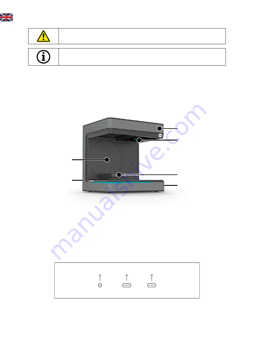
3.1 Components of the scanner
These are the main components in the scanner
2
1
4
5
6
3
No. Description
1
Connector strip (rear side)
2
Swivel bracket
3 Housing
4
Optical scan unit
5
Model support (CS.Neo2 Max = two support)
6
On/Off button
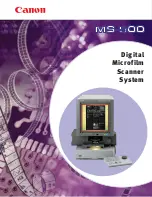
3.2 Scanner connector strip
The connector strip is located on the back of the scanner and is designed as follows:
Master
USB 3.0
USB 3.0
24V
No. Description
1
24V DC power supply socket
2
USB C 3.0 Port Master Unit
3
USB C 3.0 Port Slave Unit (CS.Neo2 Max only)
Summary of Contents for CS.Neo2
Page 1: ...www cadstar dental Instruction manual CS Neo2 CS Neo2 Pro CS Neo2 Max...
Page 15: ...EN 14 9 1 Product diagrams clearances...
Page 30: ...14 DE 9 1 Produktskizzen Abst nde...
Page 45: ...IT 14 9 1 Schizzi del prodotto e distanze...
Page 60: ...14 ES 9 1 Bocetos y espaciado de los productos...
Page 75: ...FR 14 9 1 Sch mas de produits distances...
Page 78: ...2 RU 1 3D CADstar Technology 1 1 1 1 1 CADstar 1 1 2 3D...
Page 81: ...RU 5 1 8 1 9 1 10 1 11 3D 2...
Page 82: ...6 RU 2 1 2 2...
Page 83: ...RU 7 2 3 1 2 1 2 11 13 2 4 2cm 15cm 1 2 3D 3 4 5 6 7...
Page 87: ...RU 11 5 1 24 5 2 5 3 1 6 USB 1 5 USB CADstar USB USB3 0 7...
Page 88: ...12 RU 7 1 3D 7 2 7 3 3D CADstar Technology 8...
Page 90: ...14 RU 9 1...
Page 105: ...RO 14 9 1 Diagrame produs i aprob ri...
Page 120: ...14 PL 9 1 Schemat produktu i dopuszczenia...
Page 135: ...EN 14 9 1 r n diyagramlar ve a kl klar...
Page 137: ...A 5500 Bischofshofen Tel 43 0 6462 32 880 office cadstar dental www cadstar dental...


