background image

OPERATING INSTRUCTIONS 

CAE 


2765 & 2725

 Tire  Changer

Summary of Contents for 2765

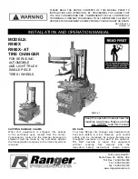
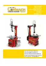
Page 1: ...OPERATING INSTRUCTIONS CAE 2765 2725 Tire Changer...
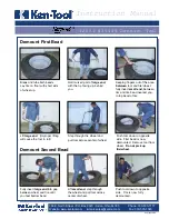
Page 2: ...24 4 0 MAINTENANCE 25 4 1 Consumables for installation maintenance and servicing 25 4 2 Safety Regulations for Oil 26 4 3 Notes 27 4 4 Maintenance or Service Plan 27 4 5 Troubleshooting Error Display...

Page 3: ...3...

Page 4: ...MED FOR ANY DAMAGES CAUSED BY FAILURE TO FOLLOW THESE INSTRUCTIONS OR THE VALID SECURITY PROVISIONS WARNING Follow the instructions to prevent injury or damage TIP Provides more information on functio...

Page 5: ...adjustment of the assembly head 4 Assembly head To assemble disassemble tires 5 Assembly tower Can be swiveled backwards 6 Rotary plate To rotate the wheel 7 Clamping claws To clamp the wheel rim 8 G...

Page 6: ...tarting position 3 The clamping claws open in the first position The middle position gently pressing the pedal allows you to close the clamping claws and set them to the wheel being used The clamping...

Page 7: ...wheel rim is not authorized for sale in some countries On some wheel rims the nut in the middle of the wheel rim is very deep meaning that for assembly or disassembly the tire has to be pushed in very...

Page 8: ...g You can place the bead breaker blade on the outside of the tire using the control lever To complete the assembly without any damage the blade must be positioned around 1 cm from the edge of the rim...

Page 9: ...the narrow bead seat is facing up To prevent damage to alloy wheels when clamping it is recommended to only clamp these from the outside and to use plastic protectors Gently press down the gear chang...

Page 10: ...e working position and release the locking device in order to bring the assembly head up to the rim flange by hand and put it on In order to do so the guide roller 3 and or the plastic contact strip f...

Page 11: ...te the assembly head Press the bead in 3 6 and 12 o clock position up to the first wheel rim depression ensuring that the tire is not compressed whilst doing so Press down the gear change pedal for th...

Page 12: ...over the wheel rim and commence the rotational motion in the same way as for the upper bead After disassembly press down on the gear change pedal to move the assembly tower so it swivels back Then re...

Page 13: ...e tire so that the tire bead is under the nose but still on the guideway of the assembly head When doing so ensure that the tire is opposite the assembly head in the wheel rim depression Start the rot...

Page 14: ...tire is positioned correctly in relation to the assembly head Start the rotational movement of the clamping plate During the assembly process ensure that the bead run is correct Failing to ensure thi...

Page 15: ...e tire over the wheel rim you can increase the air volume by removing the inner valve This must be replaced quickly afterwards Ensure that the tire has been inflated to the correct pressure Consult th...

Page 16: ...plate torque 1100 Nm Rotary plate speed 7 rpm Power supply 380 50 16 V Hz A 220 50 16 V Hz A Drive power 0 75 kW 1 10 kW Motor speed 1380 rpm Working pressure 8 10 bar 0 8 1 0 Mpa Noise emission 70 dB...

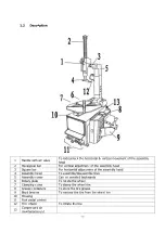
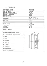
Page 17: ...17 1 5 Scale Drawing...

Page 18: ...tioning the machine always use suitable lifting and material handling equipment and consider the machine s centre of gravity The machine should only be transported with the original packaging Data Wid...

Page 19: ...1 Steel assembly head 2 Plastic contact strip 3 Tire assembly iron 4 Impact anchor 5 Seal kit and membrane for rapid air vent 6 Plastic protector for side bead breakers 7 Manual tire inflator 8 Compre...

Page 20: ...he ground conditions the guidelines and instructions of the accident prevention regulations as well as the workplace regulations must be observed when selecting an installation site When assembling on...

Page 21: ...2 6 Electrical Connection General and local regulations must be observed Therefore these steps may only be carried out by a trained professional Pay attention to the necessary supply line see technic...

Page 22: ...recommendations of the manufacturer Used media that do not meet the specific requirements or which have unauthorised contamination damage the entire hydraulic system and shorten the service life of th...

Page 23: ...side of the holes Insert the anchor bolts into the holes until they have reached an appropriate depth Tighten the nuts to the torque specified by the manufacturer Clamping thickness B varies depending...

Page 24: ...to catch any flying parts Keep people out of the danger area Tire filling must be monitored and the maximum permissible assembly air pressures must not be exceeded Only operate motor driven wheel bala...

Page 25: ...ions for mounting or dismounting of vehicle specific work An important part of the guarantee warranty is fulfilment of the maintenance plan This includes in particular ensuring cleanliness corrosion p...

Page 26: ...nt especially for 2 post lifts Eni PRECIS HVLP D Item No 00067218 Summer 15 to 45 HVLP D 32 e g Eni PRECIS HVLP D Winter under 10 HVLP D 22 e g Eni PRECIS HVLP D Preservative for ropes welds screws co...

Page 27: ...s in the tread area and plastic parts Minimum requirement Valet Pro Classic Protectant Plastic Sealant 500 ml 4 2 Safety Regulations for Oil Always observe the legal requirements or regulations for ha...

Page 28: ...r restore surface protection X Check for leaks in the hydraulic system X Check or restore surface protection or corrosion protection X Check or restore damage to the paint and components X Check or re...

Page 29: ...eplace components Pneumatic hydraulic cylinder jams or leaks Replace cylinder or replace seals Air pressure hydraulic pressure too low Increase air pressure check oil level Valve block does not respon...

Page 30: ...regulator A Pull the pressure regulator upwards to make adjustments Turn the knob clockwise to increase the pressure in the machine turn it counter clockwise to decrease OILER Check the oil level in t...

Page 31: ...should give by a maximum of 8 mm 1 2 The counter nut B and all motor fixing screws must be tightened for final fixing The final stage is to reassemble the cover PNEUMATIC LOCKING OF THE MOUNTING HEAD...

Page 32: ...ojects approx 6 7 mm over the rim flange The approach roller 3 contacts the rim flange After setting ensure that both grub screws 2 and the fixing screw 1 are secured again CHECKING AND REFILLING THE...

Page 33: ...tore them in accordance with local regulations Remove the oil from the machine and store it in accordance with local regulations Recycle all metallic substances The machine contains some substances th...

Page 34: ...34...

Page 35: ...35 6 1 Pneumatic circuit diagram 6 0 APPENDIX...

Page 36: ...36 6 2 Electric circuit diagram...

Page 37: ...37 6 3 Hydraulic circuit diagram Not relevant...

Page 38: ...Reference number Message description Description of required spare parts Spare part Item number Amount IMPORTANT Transport damages Visible defect visible transport damage note on freight forwarder del...

Page 39: ...uctions Normal wear and tear on parts requiring service to keep the product in safe working condition Any component that has been damaged during transport Other components that have not been explicitl...

Page 40: ...of operation by a suitable and approved company or facility In the case of changes or extensions to the product type an additional inspection book must be maintained and accepted Scope of Inspection...

Page 41: ...proper assembly handover and if necessary training as well as yearly maintenance carried out by an expert authorised by the manufacturer The interval between services must not exceed 12 months In cas...

Page 42: ...on Condition cylinder Condition valve Condition electrical control Condition electric buttons Condition electric switches Condition electric lines Condition hydraulic lines Condition hydraulic screws...

Reviews: