Dynaco ST-70 Restoration Module
Assembly, Installation, and Adjustment Manual
Page 3
CAE Dynaco Driver Restoration Module PC-3R – R0: 7-02
III. Assembly
A.
Building the PC Board (PC-3R)
Components are to be inserted on the non foil side and soldered on the foil side. The
sequence of assembly has been chosen so that the components with the lowest profile
(such as jumpers, low power resistors, IC’s etc.) are installed first with higher profile
components added until the highest profile components are installed last.
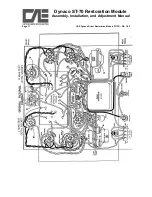
Refer to the component placement drawing (figure 1). Be sure to observe correct
orientation of polar components (capacitors). Be sure also to check with an ohmmeter
resistor values if you are not absolutely sure of how to read metal film resistor color
codes.
1. Begin by installing all of the ½ Watt
resistors. There are a total of 16 ½ Watt
resistors specified. Refer to Figure 1 (Top
View PC Board Component Placement
Diagram). The board has been designed so
that a gentle radius near the body of the
resistor will position the leads in alignment
with the associated holes in the PC Board.
Note that the ½ Watt resistors should be
inserted so that the body of the resistor
rests gently against the PC Board. After
inserting the resistor leads thru the board, a
slight bending outward of the leads will
hold the part in place until you can solder it
in place.
2. Install the Six (12) 3 Watt metal Oxide resistors. You should also gently bend the leads
of these resistors similar to the ½ Watt resistors (but of course with a greater radius). But
unlike the ½ Watt resistors, the # Watt Resistors should be spaced away from the plane of
the PC Board by 1/16” to allow for heat dissipation.
4. Install the 2 nine (9) pin miniature tube sockets. Be careful to insure that the leads fully
extend thru the PC Board and that you have sufficient tab length to obtain a solid solder
connection.
5. Install the 10 capacitors. There are 6 large values and 4 small values.


