background image

FAST-PS-M – User’s Manual 


damage to the equipment. Do not proceed beyond a CAUTION sign until all 
indicated conditions are fully understood and met. 


CAEN ELS will repair or replace any product within the guarantee period if the 

Guarantor declares that the product is defective due to workmanship or materials and 
has not been caused by mishandling, negligence on behalf of the User, accident or any 
abnormal conditions or operations. 
 

Please read carefully the manual before operating any part of the instrument 


Do NOT open the boxes


CAEN ELS d.o.o. declines all responsibility for damages or injuries caused 

by an improper use of the Modules due to negligence on behalf of the User. It is 
strongly recommended to read thoroughly this User's Manual before any kind of 
operation.  


CAEN ELS d.o.o. reserves the right to change partially or entirely the contents of this 

Manual at any time and without giving any notice. 


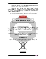
Disposal of the Product 


The product must never be dumped in the Municipal Waste. Please check your local 

regulations for disposal of electronics products. 


WARNING 

Summary of Contents for FAST-PS-M

Page 1: ...AST PS M User s Manual 1 FAST PS M Current and Voltage Controlled Monopolar Digital Power Supply Series User s Manual All Rights Reserved CAEN ELS s r l Rev 1 4 August 2017 MAGNET POWER SUPPLY SYSTEMS...

Page 2: ...FAST PS M User s Manual 2 This product is marked CAEN ELS s r l c o AREA Science Park S S 14 km 163 5 34149 Basovizza TS Italy Mail info caenels com Web www caenels com...

Page 3: ...N Trigger Input on BNC connector This manual cover the Custom Model named as following FAST PS M Cxx yyzz kkk Where xx is the Customization code yy is the maximum output current expressed in Amps zz i...

Page 4: ...ote Sensing 18 2 2 OPTIONS 19 Analog Control Input 20 Trigger Input 21 2 3 FRONT PANEL INDICATORS 22 2 4 INTERNAL PROTECTIONS 23 Earth Leakage Current 23 Earth Fuse 23 Regulation Fault 23 Input OVerCu...

Page 5: ...M User s Manual 5 Power up 34 Home Screen 34 Menu Page 35 Control Page 36 Config Page 37 Advanced Page 37 5 MECHANICAL DIMENSIONS 38 5 1 FAST PS M 3030 MECHANICAL DIMENSIONS 39 6 TECHNICAL SPECIFICAT...

Page 6: ...t Release 1 0 November 26th 2015 First Public Release 1 1 December 14th 2015 Fixed some errors and images added 1 2 July 15th 2016 Updated Images and Installation Chapter 1 3 December 21st 2016 Added...

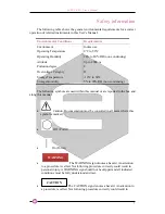
Page 7: ...C Storage Humidity 5 to 90 RH non condensing The following symbols are used within this manual or are reported in the box and along this manual Caution Documentation must be consulted in all cases whe...

Page 8: ...se read carefully the manual before operating any part of the instrument Do NOT open the boxes CAEN ELS d o o declines all responsibility for damages or injuries caused by an improper use of the Modul...

Page 9: ...instrument for possible cracks or breaks before each use Do not operate the device around explosives gas vapor or dust Always use the device with the cables provided Turn off the device before establi...

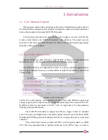
Page 10: ...igital bipolar power supply module There are available different models with different current and voltage ranges Model Name Current Voltage Maximum Power FAST PS M 3030 900 30 A 30 V 900 W FAST PS M...

Page 11: ...ture with a very high update rate more than 10 kHz These ports are connected directly to the FPGA logic and so the given packet is elaborated directly by the hardware logic This approach eliminates th...

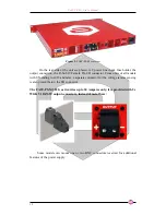
Page 12: ...or From units of all models with SN ending in x010 and later a separate connector for the voltage remote sensing is also present below the I O connector The FAST PS M 3030 as it carries up to 30 Amper...

Page 13: ...e drop that the power supply is able to compensate is of 0 5V Local Remote Fast Interface Control Mode The FAST PS unit can be controlled in three main different ways hereafter listed LOCAL control th...

Page 14: ...external event i e a hardware trigger coming from the rear BNC connector Please note that this mode of operation is obtainable only on the units that have the external trigger input connector installe...

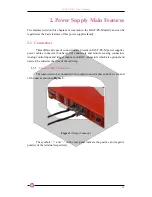
Page 15: ...pplies power cables connector bus bars I O connectors and remote sensing connectors Analog control input and trigger input are on BNC connectors which are optional and needs to be added at the time of...

Page 16: ...own in Figure 3 This type of connector offers a convenient and reliable form of connection it is suggested to connect the wire directly to the connector The suggested cross sectional area of the cable...

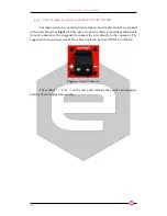
Page 17: ...installed in order to use access these available signals Figure 5 I O Connector The pin index of the D Sub 15 rear connector is summarized in the following table Pin Number Signal name 1 4 DNC 5 Magne...

Page 18: ...series allows users to decide what interlock are enabled or not set the interlock trip level i e low or high the time of intervention the time that an interlock signal has to be at the trip level befo...

Page 19: ...ut connector of the power unit Leaving S and S pins disconnected will make the power supply sense the output voltage directly at the output terminal connections When using the remote sensing feature l...

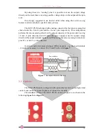
Page 20: ...that allows the FAST PS M to be controlled as an amplifier is provided on the rear panel on a BNC connector on the A socket This input is labelled as AN CTRL This input accepts signals ranging from 0...

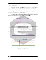
Page 21: ...at allows for this recognized values that guarantee correct operation of the trigger as listed in Table 3 Logic Level Value Low to HIGH 2 2 V High to LOW 0 7 V Table 3 Trigger Logic Levels The absolut...

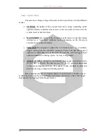
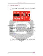
Page 22: ...n off it is regulating the ouput voltage STAT green signals the correct operation of the module diagnostics The blinking signaling the correct operation has a 1 second period OUT ON blue it signals if...

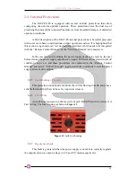
Page 23: ...e of a fault condition the power supply needs to be reset by the user before turning the power supply output back on again Different values related to a fault condition can be set and these procedures...

Page 24: ...section of the unit is sensed by a hall transducer that in conjunction with a comparator generates a signal that turns off the device The threshold value of intervention depends on the FAST PS M speci...

Page 25: ...f the FAST PS M before turning the output off again DC Link Undervoltage The FAST PS M is composed internally by a power AC DC section cascaded with a DC DC stage The voltage generated by the AC DC se...

Page 26: ...he minimum time interval for the waveform execution period is rated at 0 1 ms 100 s giving an equivalent output waveform update rate of 10 kHz In order to correctly execute the output waveform it is n...

Page 27: ...er supply to the AC source 5 Load connection Wire size selection Remote Sensing 4 First switch on Switch on checkout procedure Table 5 Installation checklist 3 2 Initial inspection Prior to shipment t...

Page 28: ...eries is designed to fit in a standard 19 equipment rack Use a support bar to provide adequate support for the power supply Desktop use The FAST PS M power supply series can be used as desktop unit 3...

Page 29: ...ndard IEC C13 plug Current rating for the connector is 10A Wire size for detachable power supply cord not longer than 2 m shall be at least 0 75 mm2 Wire size for fix installation shall be at least 1...

Page 30: ...the maximum voltage to the load will be limited to FAST PS M nominal output voltage Maximum compensation Voltage if Remote sensing is used Cable Drop Voltage Maximum compensation Voltage for all model...

Page 31: ...tive Ground i e chassis Mains Earth terminal and all metallic parts composing the box through a fuse This fuse called Earth Fuse E F is accessible form the back panel With this configuration the Outpu...

Page 32: ...FAST PS M User s Manual 32 Output terminals shall not float more than 60VDC above below chassis ground when Earth Fuse is not present WARNING...

Page 33: ...ration page of the local display Remote control is discussed in the Remote Control Manual and in the VISUAL Manual 4 1 Navigation Switch Each FAST PS M power supply module is equipped with a Navigatio...

Page 34: ...screen is the first loaded page upon power up or power cycling of the module it is shown in Figure 17 and contains information on the FAST PS M model the module IP address output current readback val...

Page 35: ...orded this means that the first fault happening does not ban the other ones to be recorded so that giving users more information permits a better investigation of the fault cause Menu Page The Menu pa...

Page 36: ...ain rectangle once pressed sends back the visualization to the Home Screen Control Page The Control Page is reachable by selecting the corresponding rectangle from the Menu Page The Control Page gives...

Page 37: ...ure 21 Config Page The firmware installed version is shown at the bottom of this page FW Version Advanced Page The Advanced Page is reachable by selecting the corresponding rectangle from the Menu Pag...

Page 38: ...FAST PS M User s Manual 38 5 Mechanical Dimensions The mechanical dimensions of the FAST PS M units are hereafter presented in units of mm in Figure 23 Figure 23 FAST PS Mechanical Drawings...

Page 39: ...FAST PS M User s Manual 39 5 1 FAST PS M 3030 Mechanical Dimensions The FAST PS M 3030 has different dimensions with respect to the other monopolar models which are reported hereafter...

Page 40: ...18 bit Voltage setting resolution 18 bit Output curret readback 24 bit Output voltage readback 24 bit Output current ripple 30 ppm FS Output current stability 50 ppm FS Output voltage stability 50 pp...

Page 41: ...s 1x Ethernet 10 100 1000 TCP IP 2x SFP ports Extra features Point by point current waveform User definable interlock thresholds active levels and timings Firmware remote update Analog control input 0...

Reviews: