background image


P R E L I M I N A R Y


Document type: 

Title: 

Revision date: 

Revision: 

User's Manual (MUT) 

 N1471 4 Channel Programmable HV Power Supply 

24/03/2010 


NPO: 

Filename: 

Number of pages: 

Page: 

00112/07:N1471.MUTx/01 N1471_REV1.DOC 

38 

10 


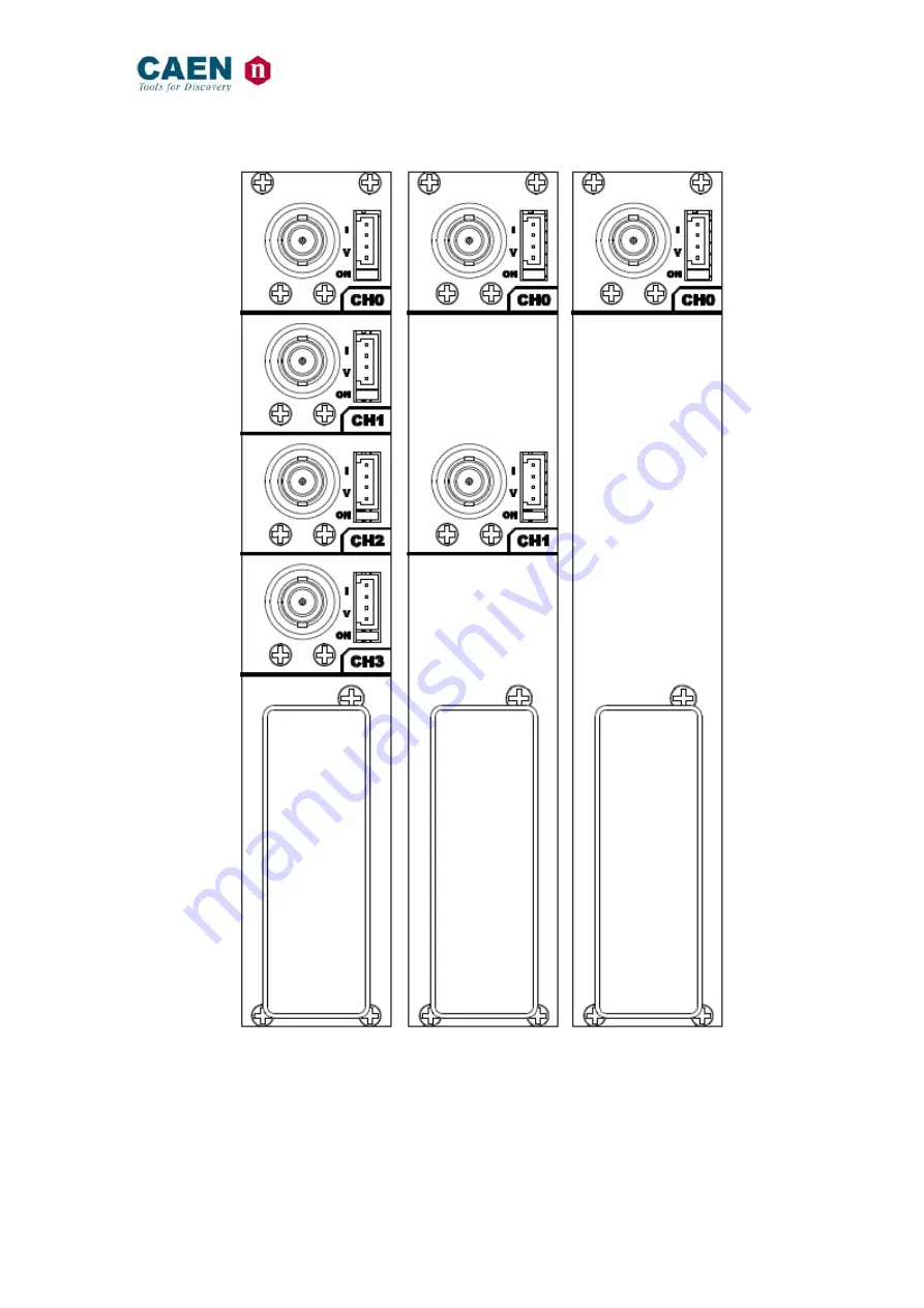
Fig. 2.2: Mod. N1471 series back panel 


Summary of Contents for N1471 Series

Page 1: ...Technical Information Manual MOD N1471 24 March 2010 Revision n 1 4 CH PROGRAMMABLE HV POWER SUPPLY MANUAL REV 1 NPO 00112 07 N1471 MUTx 01 ...

Page 2: ... responsibility for damages or injuries caused by an improper use of the Modules due to negligence on behalf of the User It is strongly recommended to read thoroughly the CAEN User s Manual before any kind of operation CAEN reserves the right to change partially or entirely the contents of this Manual at any time and without giving any notice Disposal of the Product The product must never be dumpe...

Page 3: ...2 2 4 4 Remote communication control section 13 2 5 REAR PANEL CONNECTIONS 14 2 5 1 HV Channel Output 14 2 6 TECHNICAL SPECIFICATIONS TABLE 15 3 OPERATING MODES 16 3 1 PROGRAMMABLE PARAMETERS 16 3 1 1 Boards parameters 16 3 1 2 Channel settings 17 3 2 LOCAL CONTROL 17 3 2 1 HV connection 18 3 2 2 Module settings 19 3 2 3 Channel settings 20 3 2 3 1 Group Settings 23 3 2 3 2 Smileys 26 3 3 CURRENT ...

Page 4: ...WITCHES 38 4 2 1 Local Bus termination 38 4 2 2 RS485 RS232 conversion 38 LIST OF FIGURES FIG 1 1 MOD N1471 4 CHANNEL PROGRAMMABLE HV POWER SUPPLY 7 FIG 2 1 MOD N1471 SERIES FRONT PANEL 9 FIG 2 2 MOD N1471 SERIES BACK PANEL 10 FIG 2 3 LOCAL CONTROL PANEL 11 FIG 2 4 CHANNEL CONTROL PANEL AND KILL SCHEME 11 FIG 2 5 N1471 HV STATUS CONTROL PANEL 12 FIG 2 6 N1471 ALARM ELECTRICAL SCHEME 12 FIG 2 7 N14...

Page 5: ...SCREEN 24 FIG 3 22 GROUP VSET DIGIT SELECTION SCREEN 24 FIG 3 23 GROUP CHANNEL VSET DIGIT ACCESS SCREEN 24 FIG 3 24 GROUP VSET DIGIT ADJUST SCREEN 24 FIG 3 25 GROUP VSET DIGIT CONFIRM SCREEN 25 FIG 3 26 CHANNEL VSET DE SELECT SCREEN 25 FIG 3 27 GROUP EXIT SCREEN 25 FIG 3 28 USB COMMUNICATION DIAGRAM 27 FIG 3 29 RS232 COMMUNICATION DIAGRAM 28 FIG 3 30 RS485 COMMUNICATION DIAGRAM 28 FIG 3 31 ETHERNE...

Page 6: ...71 4 Channel Programmable HV Power Supply 24 03 2010 1 NPO Filename Number of pages Page 00112 07 N1471 MUTx 01 N1471_REV1 DOC 38 6 TABLE 2 1 POWER REQUIREMENTS 8 TABLE 2 2 INTERLOCK OPERATION 13 TABLE 2 3 MOD N1471 CHANNEL TECHNICAL SPECIFICATIONS 15 TABLE 3 1 SMILEYS LIST 26 ...

Page 7: ...e programmed value by more than 2 of set value minimum 10V Programmable VMAX protection limit OVERCURRENT detection if a channel tries to draw a current larger than its programmed limit it enters TRIP status keeping the maximum allowed value for a programmable time TRIP before being switched off Channels can be enabled or disabled individually through the Interlock logic Module control can take pl...

Page 8: ...able HV Power Supply 24 03 2010 1 NPO Filename Number of pages Page 00112 07 N1471 MUTx 01 N1471_REV1 DOC 38 8 2 Technical specifications 2 1 Packaging The Model N1471 is housed in a single width NIM module 2 2 Power requirements Table 2 1 Power requirements Voltage Current 12 V 850 mA 12 V 850 mA ...

Page 9: ...vision date Revision User s Manual MUT N1471 4 Channel Programmable HV Power Supply 24 03 2010 1 NPO Filename Number of pages Page 00112 07 N1471 MUTx 01 N1471_REV1 DOC 38 9 2 3 Front and back panel Fig 2 1 Mod N1471 series front panel ...

Page 10: ...type Title Revision date Revision User s Manual MUT N1471 4 Channel Programmable HV Power Supply 24 03 2010 1 NPO Filename Number of pages Page 00112 07 N1471 MUTx 01 N1471_REV1 DOC 38 10 Fig 2 2 Mod N1471 series back panel ...

Page 11: ...Y SWITCH Parameter and Mode setting 2 4 2 Channel control section Fig 2 4 Channel control panel and Kill scheme NAME TYPE FUNCTION HV_EN OFF KILL 3 POS SWITCH Channel Enable and turning OFF KILL 1 ON RED LED HV On enabled REMOTE KILL AMP 280370 2 The channel is KILLED as no current flows across the 1Kohm resistor this is achieved either as the 1 2 contacts are open or as a 4 6Vdc voltage is fed to...

Page 12: ...D LEMO CONN Out Alarm status signaled active LOW INTERLOCK RED LED LEMO CONN In Interlock signal 2 4 3 1 Alarm signal Fig 2 6 N1471 ALARM electrical scheme Alarm signal output signal electrical scheme is reported in the figure above The maximum output is 400mA 12V on Pins 2 4 3 2 Interlock signal Fig 2 7 N1471 INTERLOCK electrical scheme A schematic diagram of the Interlock input is shown in the f...

Page 13: ...rent between pin 2 and pin 3 ENABLED INTERLOCK The front panel Interlock LED is ON when the INTERLOCK is enabled as INTERLOCK is enabled channels are turned off at the fastest available rate regardless the RAMP DOWN setting 2 4 4 Remote communication control section Fig 2 8 Remote communication control and RS485 I O RS232 IN electrical scheme NAME TYPE FUNCTION IN AMP 280371 2 RS485 Input 2 adapta...

Page 14: ...r panel connections 2 5 1 HV Channel Output Fig 2 9 HV Channel panel and test point electrical scheme NAME TYPE FUNCTION MON AMP 280371 2 Vout Iout Test point OUT SHV HV Channel Output The test points allow to monitor the Channel Output Voltage and Current according to the following conversion VMON Voltage level 1V 1 5 kV 1 readout same polarity as channel IMON Voltage level 1V 66 µA 3 readout pos...

Page 15: ...output voltage varies in order to keep the output current lower than the programmed value Overcurrent lasting more than set value 1 to 9999 causes the channel to trip Output voltage will drop to zero either at the Ramp down rate or at the fastest available rate depending on Power Down setting in both cases the channel is put in the OFF state If trip INFINITE overcurrent lasts indefinitely band wid...

Page 16: ...llowed in LOCAL mode only see 3 2 2 include Parameter Function Display Power Monitor Module power supply status Termination Monitor Local Bus termination status ON OFF HV Clock Monitor Sync clock frequency 200 10 kHz correct value Local Bus Baud Rate Monitor Set 9600 19200 38400 57600 115200 Baud Local Bus Address Monitor Set Local Bus address for remote communication 0 31 USB Baud Rate Monitor Se...

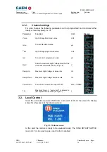
Page 17: ...ue Volt Iset Current Limit programmed value µA MaxV Absolute maximum High Voltage level that the channel is allowed to reach see 2 6 V Ramp Up Maximum High Voltage increase rate V s Ramp Down Maximum High Voltage decrease rate V s Power Down Power Down mode after channel TRIP KILL or RAMP Trip Maximum time an overcurrent is allowed to last expressed in seconds see 2 6 s 3 2 Local Control Insert th...

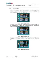
Page 18: ...L 3 POS SWITCH of each channel is set to OFF the Display will show the following message in the left lower row Fig 3 2 Channel OFF status screen now connect the HV cable linking the outputs to the loads to be supplied and enable the HV outputs switching the HV_EN OFF KILL 3 POS SWITCH in the HV_EN position the Display will show the following message in the left lower row Fig 3 3 Channel ON status ...

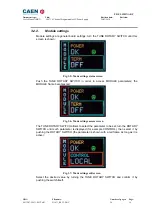
Page 19: ...de settings status screen Push the TUNE ROTARY SWITCH in order to access MODULE parameters the MODULE frame becomes red Fig 3 6 Mode settings access screen The TUNE ROTARY SWITCH allows to select the parameter to be set turn the ROTARY SWITCH until such parameter is displayed for example CONTROL then select it by pushing the ROTARY SWITCH the parameter is shown with a red frame as long as it is ac...

Page 20: ...E ROTARY SWITCH at this point the frame of the left upper row channel number becomes red and the channel is selected Fig 3 8 Channel settings edit screen Turn the TUNE ROTARY SWITCH until the parameter to be set for example VSET is displayed in the right lower row Fig 3 9 Channel VSET select screen Push the TUNE ROTARY SWITCH at this point the parameter is selected its frame is shown in red and it...

Page 21: ...1 Fig 3 11 Channel VSET digit selection screen Push the TUNE ROTARY SWITCH at this point the value digit becomes yellow and can be edited Fig 3 12 Channel VSET digit access screen Turn the TUNE ROTARY SWITCH until the digit reaches the desired value Fig 3 13 Channel VSET digit adjust screen Confirm it by pushing the TUNE ROTARY SWITCH the edited digit returns blue Fig 3 14 Channel VSET digit confi...

Page 22: ...SWITCH until the parameter name returns blue Fig 3 15 Channel VSET confirm screen Push the TUNE ROTARY SWITCH in order to de select the parameter the frame returns to blue Fig 3 16 Channel VSET de select screen It is now possible to set another parameter note that the POWER DOWN and IMRANGE setting has not digits to be edited but two options TRIP KILL and HIGH LOW respectively Fig 3 17 Channel KIL...

Page 23: ... changed while one channel is ON the channel is turned OFF and the left lower row reports ILK Interlock if the channel is OFF it can not be turned ON until it is enabled according to the Interlock logic see 3 1 1 3 2 3 1 Group Settings Group settings allow to broadcast the same parameter value to all channels In order to operate Group settings Turn the TUNE ROTARY SWITCH until ALL is displayed in ...

Page 24: ...mon to all channels pre set value is picked from Channel 0 it is now possible to change the parameters value Fig 3 21 Group VSET access screen Turn the TUNE ROTARY SWITCH until the value digit to be edited is shown in blue the parameter name in yellow Fig 3 22 Group VSET digit selection screen Push the TUNE ROTARY SWITCH at this point the value digit becomes yellow and can be edited Fig 3 23 Group...

Page 25: ...ue Fig 3 25 Group VSET digit confirm screen Once all the digits are set to the desired value turn the TUNE ROTARY SWITCH until the parameter name returns blue Push the TUNE ROTARY SWITCH in order to de select the parameter the frame returns to blue when the parameter is not active the parameter status of the four channels is shown Fig 3 26 Channel VSET de select screen In order to go to individual...

Page 26: ...gative offsets The absolute value of delivered current can be quantified by following the steps below 1 Turn on the module after a warm up of about 30 minutes with operating voltage and load disconnected no link between N1471 and detectors then read the monitored current value Imon I1 offset 2 Turn off the channel and connect the load 3 Turn on the channel with the same voltage set as point 1 4 Wa...

Page 27: ...SB B type port the featured controller the FT232BM chip requires drivers freely available at http www ftdichip com Drivers VCP htm the site also provides installation instructions for all OS s http www ftdichip com FTDocuments htm The connection can be performed via terminal emulator such as HyperTerminal configured as follows baud rate 9600 the same set on the N1471 See 3 2 2 Data bits 8 Parity n...

Page 28: ... connected to the PC RS232 port and the subsequent ones daisy chained through the COMM IN OUT as explained in 3 4 1 3 in this case communication with the chained modules is achieved through the USB RS485 Communication Protocol see 3 5 All modules must be assigned a LOCAL BUS ADDRESS see 3 1 1 different from one another and the last one must be terminated see 4 2 1 3 4 1 3 RS485 communication Fig 3...

Page 29: ...icate via Ethernet with one or more daisy chained N1471 modules through the NIM8301 Fan Unit6 Communication via Ethernet is possible only through the USB RS485 Communication Protocol The single module or the first module of the daisy chain must be connected to the Fan Unit RS232 port through the cable adapter see figure below connected to the N1471 COMM IN port SW 200 201 switch placed on the Micr...

Page 30: ...yed 3 4 2 1 Remote Control Main Menu Fig 3 33 Main Menu Type D to set monitor channels parameters Type F to format the EEPROM Type G to monitor board status Type U to upgrade the firmware Type Q to exit the program 3 4 2 2 Remote Control General Menu By typing G it is possible to access the General Menu which includes the board s general settings Fig 3 34 Board Status Menu 3 4 2 3 Remote Control C...

Page 31: ... change one parameter point the parameter with the arrow keys see figure below and type the desired value confirm by pressing Enter Power and Power Down can be changed using the Space bar Fig 3 36 PC keyboard When one parameter is active by typing G it is possible to make a group setting i e broadcast the same value to all channels the parameter becomes active on all channels see figure Fig 3 37 C...

Page 32: ...n the following menu is shown Fig 3 39 Firmware Upgrade Menu 2 At this point it is necessary to upload the updated firmware If HyperTerminal is used it is necessary to perform Transfer and Send Text File operations by selecting the file N1471 xxx 3 4 2 5 Remote Control format EEPROM By typing U it is possible to access the format EEPROM menu Fig 3 40 Format EEPROM Menu After the FORMAT command all...

Page 33: ...rmat response in case of error String Function Units BD CMD ERR Wrong command Format or command not recognized BD CH ERR Channel Field not present or wrong Channel value BD PAR ERR Field parameter not present or parameter not recognized BD VAL ERR Wrong set value Min or Max BD LOC ERR Command SET with module in LOCAL mode Each string is terminated by CR LF Format response in case of correct comman...

Page 34: ...PAR MVMIN Read out MAXVSET minimum value 0 V BD xx CMD MON CH X PAR MVMAX Read out MAXVSET maximum value 8100 V BD xx CMD MON CH X PAR MVDEC Read out MAXVSET number of decimal digits BD xx CMD MON CH X PAR RUP Read out RAMP UP value XXX V S BD xx CMD MON CH X PAR RUPMIN Read out RAMP UP minimum value 1 V S BD xx CMD MON CH X PAR RUPMAX Read out RAMP UP maximum value 500 V S BD xx CMD MON CH X PAR ...

Page 35: ...KILL via front panel Bit 12 ILK 1 Ch in INTERLOCK via front panel Bit 13 NOCAL 1 Calibration Error Bit 14 15 N C 3 5 4 MONITOR commands related to the module The following table shows the strings to be used to handle monitor commands related to the module String Function Units BD xx CMD MON PAR BDNAME Read out module name N1471 BD xx CMD MON PAR BDNCH Read out number of Channels present 4 BD xx CM...

Page 36: ... set to the 0 4 values When X 4 the command is issued to all 4 Channels String Function Units BD xx CMD SET CH X PAR VSET VAL XXXX X Set VSET value BD xx CMD SET CH X PAR ISET VAL XXXX XX Set ISET value BD xx CMD SET CH X PAR MAXV VAL XXXX Set MAXVSET value BD xx CMD SET CH X PAR RUP VAL XXX Set RAMP UP value BD xx CMD SET CH X PAR RDWN VAL XXX Set RAMP DOWN value BD xx CMD SET CH X PAR TRIP VAL X...

Page 37: ... for each channel on the front panel see 2 4 2 In order to change the polarity the unit must be switched off and wait for the complete discharge of the capacitors then remove the side covers thereby making access to the Printed Circuit Boards Antistatic Gloves must be worn before touching any internal part Lay down the unit NIM crate connector on the right and the front panel on the left component...

Page 38: ...nector side Always pull and plug the diode bridge box by holding it on the handle pointed by the arrow in Fig 4 1 wearing antistatic gloves 4 2 Internal switches Fig 4 2 Dip switch position 4 2 1 Local Bus termination The SW 1 3 switch placed on the Microcontroller board inside the module behind the Remote communication control section see 2 4 4 allows to terminate the Local Bus for daisy chain pu...

Reviews: