NGPS – User’s Manual
25
1.6
Trigger and Analog Control inputs
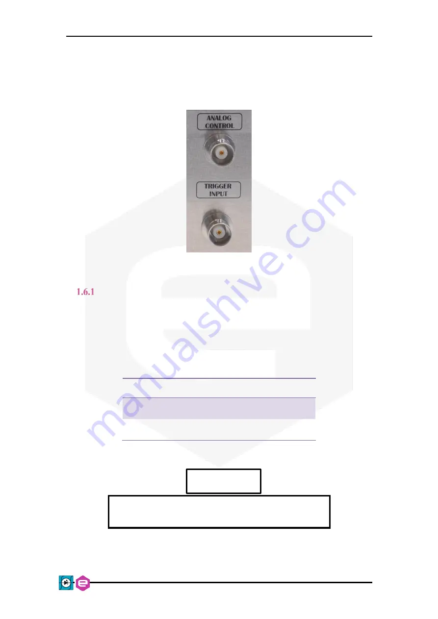
On the rear side of the NGPS there are two BNC input connectors, as shown in
, which can be used as trigger and analog control inputs.
Figure 8:
Trigger and analog input connectors
Trigger Input
The trigger input accepts TTL (5V) and LVTTL (3.3V) compatible signals and
should be driven by a low-impedance source or generator.
The logic levels are subject to a hysteresis to guarantee the correct trigger
operation, as listed in
Logic Level
Value
Low-to-HIGH
> 2.2 V
High-to-LOW
< 0.7 V
Table 6:
Trigger logic levels
The absolute maximum rating for the trigger input signal is
of
5.5 V
(a higher voltage level applied to this input can
seriously damage the device).
A visual representation of the voltage levels for the trigger operation is
presented in
CAUTION


