Document type:
Title:
Revision date:
Revision:
User's Manual (MUT)
Mod. V1724 8 Channel 14bit - 100MS/s Digitizer
06/11/2007
7
NPO:
Filename:
Number of pages:
Page:
00103/05:V1724x.MUTx/07 V1724_REV7.DOC
63
32
Table 3.3 : Front Panel I/Os default setting
Nr.
Direction
Description
0
out
Ch 0 Trigger Request
1
out
Ch 1 Trigger Request
2
out
Ch 2 Trigger Request
3
out
Ch 3 Trigger Request
4
out
Ch 4 Trigger Request
5
out
Ch 5 Trigger Request
6
out
Ch 6 Trigger Request
7
out
Ch 7 Trigger Request
8 out Memory
Full
9 out Event
Data
Ready
10 out Channels
Trigger
11 out RUN
Status
12
in
Trigger Time Tag Reset (active low)
13
in
Memory Clear (active low)
14 -
RESERVED
15 -
RESERVED
3.7. Analog
Monitor
The board houses a 12bit (100MHz) DAC with 0÷1 V dynamics on a 50 Ohm load (see
Fig. 1.1), whose input is controlled by the ROC FPGA and the signal output (driving 50
Ohm) is available on the MON/
Σ
output connector. MON output of more boards can be
summed by an external Linear Fan In.
This output is delivered by a 12 bit DAC.
The DAC control logic implements five operating modes:
-
Trigger Majority Mode ( Monitor Mode = 0)
-
Test Mode (Monitor Mode = 1)
-
Analog Monitor/Inspection Mode (Monitor Mode = 2)
-
Buffer Occupancy Mode (Monitor Mode = 3)
-
Voltage Level Mode (Monitor Mode = 4)
Operating mode is selected via Monitor Mode register (see § 4.32)
N.B.: this feature is not available on the Mod. V1724LC
3.7.1.
Trigger Majority Mode (Monitor Mode = 0)
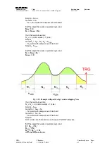
It is possible to generate a Majority signal with the DAC: a voltage signal whose
amplitude is proportional to the number of channels under/over (see § 4.12) threshold
(1 step = 125mV); this allows, via an external discriminator, to produce a global trigger
signal, as the number of triggering channels has exceeded a particular threshold.

