Document type:
Title:
Revision date:
Revision:
User's Manual (MUT)
Mod. V1724 8 Channel 14bit - 100MS/s Digitizer
06/11/2007
7
NPO:
Filename:
Number of pages:
Page:
00103/05:V1724x.MUTx/07 V1724_REV7.DOC
63
57
4.30.
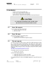
Set Monitor DAC (0x8138; r/w)
Bit
Function
[11:0] This register allows to set the DAC value (12bit)
This register
allows to set the DAC value
in Voltage level mode (see § 2.7).
LSB = 0.244 mV, terminated on 50 Ohm.
4.31.
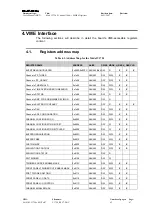
Board Info (0x8140; r)
Bit
Function
[15:8] Memory size (Mbyte/channel)
[7:0]
Board Type:
0 = V1724
4.32. Monitor
Mode
(0x8144;
r/w)
Bit
Function
[2:0]
This register allows to encode the Analog Monitor (see § 3.7) operation:
000 = Trigger Majority Mode
001 = Test Mode
010 = Analog Monitor/Inspection Mode
011 = Buffer Occupancy Mode
100 = Voltage Level Mode
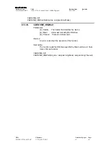
4.33.
Event Size (0x814C; r)
Bit
Function
[31:0] Nr. of 32 bit words in the next event
4.34.
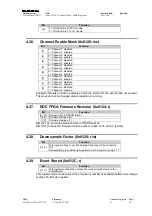
Analog Monitor (0x8150; r/w)
Bit
Function
[21,20]
Magnify factor:
00 = 1x
01 = 2x
10 = 4x
11 = 8x
[19]
Offset sign (0=positive; 1=negative)
[18:8] Offset
Value
[7]
0 = Channel 7 disabled
1 = Channel 7 enabled
[6]
0 = Channel 6 disabled
1 = Channel 6 enabled
[5]
0 = Channel 5 disabled
1 = Channel 5 enabled
[4]
0 = Channel 4 disabled
1 = Channel 4 enabled
[3]
0 = Channel 3 disabled
1 = Channel 3 enabled
[2]
0 = Channel 2 disabled
1 = Channel 2 enabled
[1]
0 = Channel 1 disabled
1 = Channel 1 enabled
[0]
0 = Channel 0 disabled


