- Lepton
9
- Technical Information Manual
25
Evaluation Board Overview
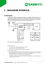
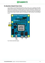
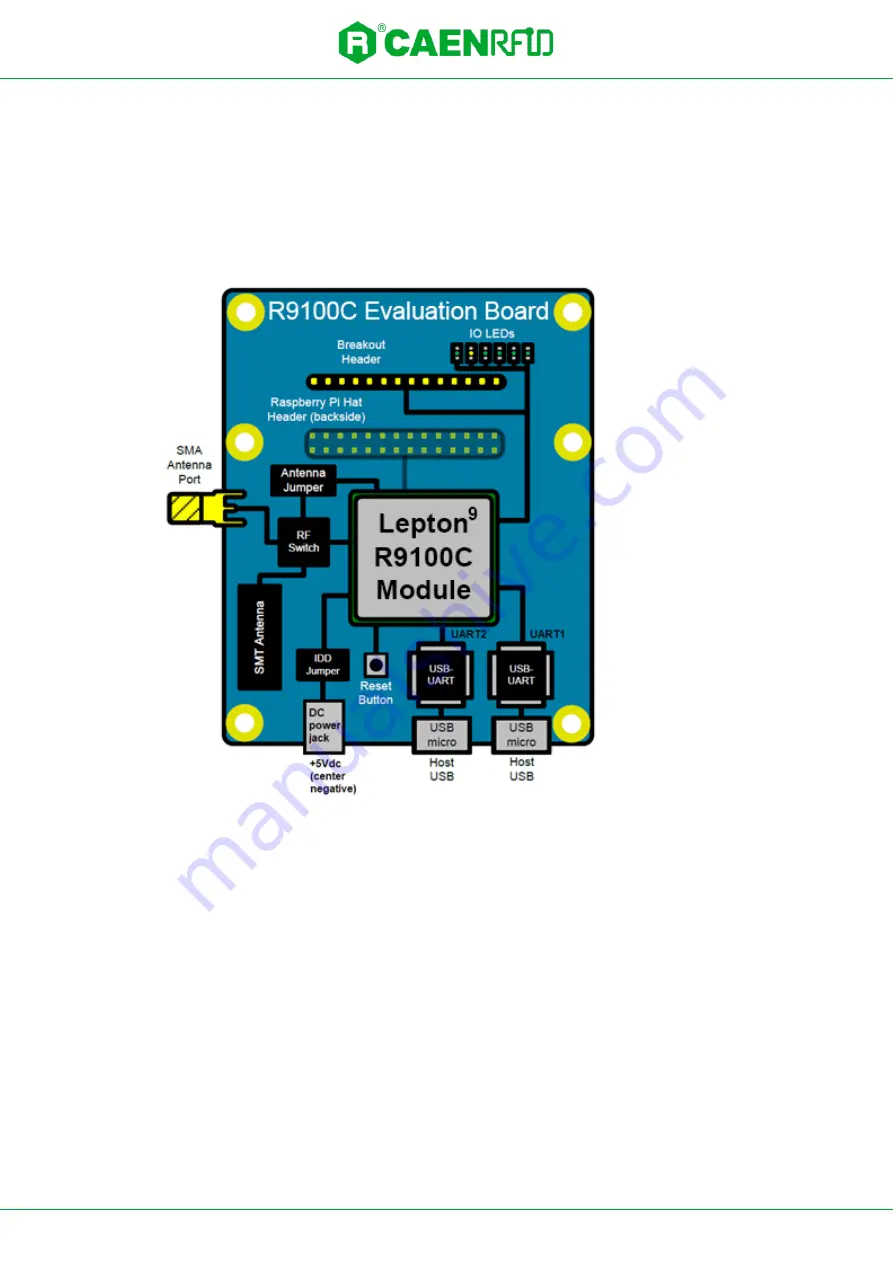
A block diagram of the WRHML37XEVBX Evaluation Board is shown in
Diagram. It shows the most notable components and connections on the PCB. The block diagram shows the
Lepton
9
R9100C
module’s
main connections: power, RF, and UART communication. The power for the
Lepton
9
R9100C is provided by a +5V AC/DC adapter at DC power jack J13 (inner pin is the GND, outer is
the +5V). The RF signal is connected to an RF switch which can then connect to either the on-board surface
mount antenna or the SMA connector. UART communication with Lepton
9
R9100C can be connected via
the USB- UART IC (using a USB micro cable), via the Raspberry Pi HAT connector, or via the breakout
header.
Fig. 5.2: Evaluation Board Block Diagram

