Lepton
9
- Technical Information Manual
11
3
HARDWARE INTERFACE
Introduction
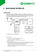
An example Lepton
9
R9100C system-level block diagram for an embedded system is shown in
Lepton9 R9100C - Example of Block
Diagram. This figure shows the electrical connections that may and
must be made to control the Lepton
9
R9100C. In the figure, the required connections are illustrated with
solid lines. Recommended and optional connections are illustrated with different dotted and dashed line
patterns. More details for each connection are listed in the following paragraphs.
Fig. 3.1: Lepton
9
R9100C - Example of Block Diagram
Required connections:
•
VDC_IN and GND are required to power the Lepton
9
R9100C.
•
RF is required to connect to the UHF RFID antenna.
•
UART1 Tx and Rx are required to communicate with the system host.
Recommended connections:
•
nRST is used to reset the Lepton
9
R9100C if UART communication is not available. This connection is
highly recommended. This pin is internally driven strong low during software resets, so it should only
be driven externally by an open drain signal. It must not be driven strong high.
•
TST and BSL_SEL shall be used for the FW recovery/upgrade procedure.
To start the Boot Strap Loader of Lepton
9
internal microcontroller NRST, TST and BSL_SEL signals shall
be driven as in the picture below:


