Page 7
3.1
Adjusting and Locking the Aperture
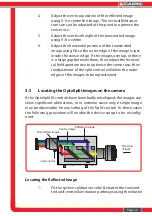
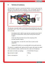
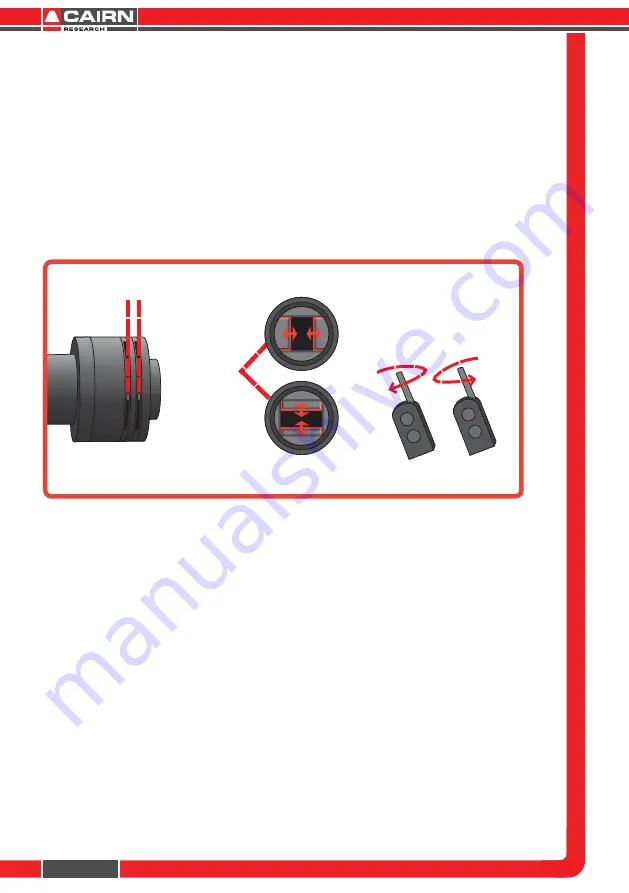
The OptoSplit III is supplied with an adjustable rectangular aperture
that allows the user to determine the ROI both vertically and
horizontally. Once the ROI has been defined, the aperture can be
locked in place using the aperture adjusters. (See diagram below.)
In order to adjust the ROI, adjust each of the two levers on the input
port of the OptoSplit III until the desired area is defined on the camera.
If you wish to lock the aperture in place, then tighten the levers by
rotating them clockwise, and to loosen them rotate anti-clockwise.
3.2
Adjusting the Position of the Images
For successful image separation it is necessary to first define the field of view,
and ensure the three optical pathways are overlaid.
It is possible to separate the images by rotating the Split control in the
clockwise sense, however image distortion will be evident when overlaying
the two halves of the image.
The imaging procedure that follows assumes a Triple Filter Cube is installed
and the full image is being monitored.
To begin, set a convenient sized aperture using the input aperture levers so
the edges of the aperture are just visible within the field of view vertically, and
restrict the field to just under 33% of the horizontal dimension.
It is also important to note that here the reflected image (that with the
shortest wavelength), is depicted as being to the right of the screen. You will
be able to identify this image easily after seperating all three as it will move
with adjustments to the V1 control, but not adjustments to the V2 control.
Aperture adjusters
Aperture
mechanism
Turn the aperture handles
clockwise to lock and unlock
the aperture adjusters


