


Page 11
6.
The remaining hex screws should then be
re-tightened & the shutter plate removed.
7.
If the microscope image is in focus down the eye-
pieces, but blurred when viewed through the
OptoSplit III with the aperture is in focus, then the
microscope C-mount is not parfocal with the eye-
pieces. The side port should be adjusted as described
by the microscope manufacturer if parfocality is
required (recommended), or the microscope focus
control can be used to independently bring the image
into sharp focus on the OptoSplit III field aperture.
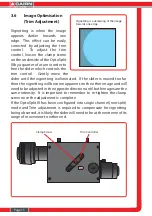
3.4
Dual and Single Image Modes of Use
The OptoSplit III can be setup in single channel or two channel
(OptoSplit) modes, by simply exchanging the filter cube & adjusting
the field aperture. Single image or “bypass” mode is the simplest of
these, only requiring the field diaphragm to be fully opened to enable
operation in full frame mode. When using the OptoSplit III with the
regular OptoSplit II cubes for dual image splitting, the setup is similar
to that described above for three channel operation, but the second
reflected image is not present. To fully align an OptoSplit II cube in the
OptoSplit III, the adjustment sequence is given below:
1.
Set a convenient sized aperture using the input
aperture levers so the edges of the aperture are just
visible within the field of view vertically, and restrict
the field to just under 50% of the horizontal
dimension.
2.
Identify the image that is reflected by the cube
dichroic mirror by adjustment of the V1 vertical
control.
3.
Rotate the separation control counter-clockwise until
the reflected image outer edge is located just inside
the edge of the sensor.


