background image

Page 3

In  most  applications,  the  dichroic  beamsplitter(s)  will  have  longpass 

characteristics,  so  the  longer  wavelength  of  the  filters  should  be 

located  in  the  straight  through  filter  position,  and  the  shorter 

wavelength filters in the second/third position. 

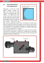
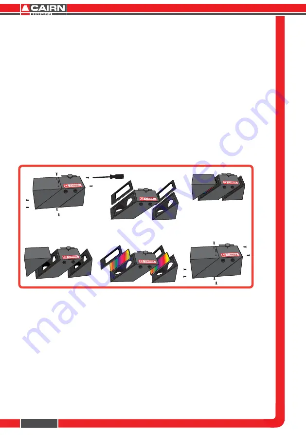
2 .2    Installing Dichroic Mirrors into the Cairn Filter Cube

To fit your dichroic mirrors into the Cairn Filter Cube remove each of the 

eight screws that secure the three sections together.  You will then be 

able to gently pull the cube apart.  There is one steel locating rod in 

each  part  of  the  cube  to  ensure  the  correct  alignment  when  it  is 

reassembled.  Once the sections of the cube are seperated remove the 

dichroic holder and place the dichroic mirror(s) (active side down) into 

the  rectangular  recess(es).    Then  simply  replace  the  holder  and 

reassemble the cube and tighten the screws.

2.3 

Inserting the Cairn Filter Cube into the OptoSplit III

The  Cairn  filter  cube  is  designed  to  be  easily  accessible  in  order  to 

facilitate quick and easy changes of filter sets.  Access to the filter cube 

mount is gained by removing the access panel using the two handles 

to pull gently and firmly.  The filter cube mount will now be visible.  The 

mount attached to the rear of the Cairn Filter Cube is designed to mate 

with the bracket on the internal wall of the OptoSplit III, so that the 

small handle on top of the cube will be facing out.  Once the Cairn Filter 

Cube is mounted successfully, replace the access panel using the two 

handles.  (See over for diagram.)

Remove the 8 screws and 

seperate the three sections.

Remove the dichroic holders and 

carefully place the mirror(s) in 

the recess(es) active side down.

Re-assemble the cube 

and replace the screws.

Summary of Contents for OptoSplit III

Page 1: ...www cairn research co uk Free Phone 08453301267 UK only Tel 44 0 1795590140 Fax 44 0 1795594510...

Page 2: ......

Page 3: ......

Page 4: ...rt department who are always willing to help e mail tech cairn research co uk Note Please do not adjust any control before reading this manual The OptoSplit is supplied pre aligned and centred please...

Page 5: ...plit III in the Lightpath Operation of the OptoSplit III Adjusting and Locking the Aperture Adjusting the Position of the Images Focussing the Camera on the Aperture Dual and Single Image Modes of Use...

Page 6: ...hin the camera frame Images can be acquired using any imaging software and processed either manually off line or using an appropriate analysis tool such as the Splitview module in Universal Imaging s...

Page 7: ...ces for three 25mm filters These are held in place by locking rings which can be removed using the tool provided To fit a filter remove the locking ring and place the filter orientated so that the arr...

Page 8: ...ular recess es Then simply replace the holder and reassemble the cube and tighten the screws 2 3 Inserting the Cairn Filter Cube into the OptoSplit III The Cairn filter cube is designed to be easily a...

Page 9: ...Page 4 Remove the access panel using the two handles Mounting bracket Replace the access panel using the two handles Mount the filter cube onto the brackect on the interior of the OptoSplit II...

Page 10: ...lear image can be seen the camera should be switched off and removed from the microscope The OptoSplit III should then be fitted on to the microscope with the diaphragm orientated toward the output of...

Page 11: ...cus The image should line up with the edges of the aperture and should not have any rotation or slant in either direction 3 Operation of the OptoSplit III The OptoSplit III uses a single control for a...

Page 12: ...e overlaid It is possible to separate the images by rotating the Split control in the clockwise sense however image distortion will be evident when overlaying the two halves of the image The imaging p...

Page 13: ...ontrol anti clockwise will seperate the reflected and transmit ted images symmetrically on the horizontal axis whilst the Centre image will not deviate Note To prevent calibration of the OptoSplit III...

Page 14: ...ong the vertical axis and allow for adjustments to be made independently of the Reflected image Adjustments to the H3 controller will move the Transmitted image along the horizontal axis Adjustments t...

Page 15: ...ken the two hex screws that retain the output rotating ring to allow the camera to turn in the C mount 3 Slightly loosen the single hex screw which locks the focussing ring 4 Rotate the focussing ring...

Page 16: ...erture Single image or bypass mode is the simplest of these only requiring the field diaphragm to be fully opened to enable operation in full frame mode When using the OptoSplit III with the regular O...

Page 17: ...e size to optimise the sensor use then readjustment of the split control will allow the outer edges of the images to be repositioned 3 5 Locating the OptoSplit images on the camera If the OptoSplit II...

Page 18: ...ra field horizontally Locating the Transmitted Image 1 Move the shutter from the transmitted to the reflected illumination pathway the calibration cube should remain in place 2 With the reflected imag...

Page 19: ...ontrol 4 If after scanning the horizontal axis no image can be found again open the input aperture slightly repeat step 3 5 Once the edges of the aperture have been found reduce the input aperture as...

Page 20: ...he slider is moved too far then the vignetting will become apparent on the other image and will need to be adjusted in the opposite direction until both images are the same intensity It is important t...

Page 21: ...e to give precise symmetrical control of the degree of separation whilst maintaining identical path lengths A half size fully silvered mirror at the output port for recombining the images Fine adjustm...

Page 22: ...age 17 5 Technical Support E mail tech cairn research co uk Web http www cairn research co uk Address Cairn Research Graveney Road Faversham Kent ME13 8UP Telephone 44 0 1795590140 Fax 44 0 1795594510...

Page 23: ...Page 18 In addition to designing and manufacturing our own products we are also proud distributors for the following companies...

Page 24: ......

Page 25: ......

Reviews: