5-1
SECTION 5 – DIAGRAMS
5.1 GENERAL
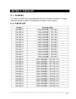
This section contains the interconnect diagrams and top assembly diagrams for the
TrueWave series. The interconnect diagrams can be used to understand the theory of
operation and as an aid in troubleshooting the unit.
5.2 DIAGRAMS
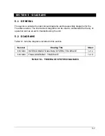
Table 5-1 lists the diagrams included in this section.
Number
Drawing Title
Sheet
6161469
INTERCONNECT DIAGRAM, SYSTEM, TRUEWAVE
1 of 2
5161469
FINAL ASSEMBLY, TRUEWAVE
1 of 8
TABLE 5-1. TRUEWAVE SYSTEM DIAGRAMS
Summary of Contents for TrueWave TW1750
Page 2: ......
Page 4: ...ii This page intentionally left blank ...
Page 10: ...TABLE OF CONTENTS TW SERIES viii This page intentionally left blank ...
Page 36: ...MAINTENANCE AND TROUBLESHOOTING TW SERIES 2 16 This page intentionally left blank ...
Page 80: ...CALIBRATION TW SERIES 3 44 This page intentionally left blank ...


