SERVICE MANUAL
MAINTENANCE AND TROUBLESHOOTING
2-5
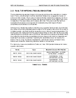
Fault Symptom
Troubleshooting / Corrective Action
Unit comes up normally. Upon
relay closure unit display “PS
FAULT 1” indicating that a
redundant overvoltage has
occurred.
•
Check external sense and power lead
wiring.
•
If problem persists, de-energize unit and
perform disassembly steps 2.6.1 to 2.6.9.
Inspect the 5161489-01 cable for proper
installation. Re- assemble unit and test.
Note:
If the previous procedures fail to isolate the faulty module, contact the Elgar
Customer Service Department for additional assistance.
2.6 DISASSEMBLY & RE-ASSEMBLY
The following is the disassembly procedure for the TW system. Once disassembled, the
unit can be re-assembled by performing the following procedure in reverse and referring
to the Final Assembly drawing 5161469 located in Section 5 of this manual.
WARNING
Prior to beginning disassembly procedures, ensure that AC
power has been disconnected from the TW system.
During re-assembly of the unit, it is very important that all removed cable-ties and
adhesives are replaced and that cables are routed as they were originally. Incorrect
routing of cables could lead to fan blade obstruction resulting in noisy operation,
restricted airflow or cable damage. In addition, special care must be taken so that no
exposed connector pins are damaged or broken.
QUICK REFERENCE GUIDE
To Remove:
Perform Steps:
Fan Panel Assembly
2.6.1 – 2.6.5
Power Module or Amplifier
2.6.1 – 2.6.19
Housekeeping Board
2.6.1 – 2.6.8
Signal Board
2.6.1 – 2.6.14
Front Panel Assembly
2.6.1 – 2.6.8
Analog Board
2.6.1 – 2.6.9
Control Board
2.6.1 – 2.6.9
Rear Panel Assembly
2.6.1 – 2.6.20
Summary of Contents for TrueWave TW5250
Page 2: ......
Page 4: ...ii This page intentionally left blank...
Page 10: ...TABLE OF CONTENTS TW SERIES viii This page intentionally left blank...
Page 36: ...MAINTENANCE AND TROUBLESHOOTING TW SERIES 2 16 This page intentionally left blank...
Page 80: ...CALIBRATION TW SERIES 3 44 This page intentionally left blank...


