Page 16
Revised 01/01/04
Cal Zone Quest 2000 Ozonator
Your new Cal Zone Quest 2000 Ozonator is a state-of-the-art bacteria killing machine. This unit will assist you in
maintaining clean and clear spa water, while saving you time and expense with spa chemicals.
Operation
Your Cal Zone Quest 2000 Ozonator will automatically operate during the filter cycles. When the spa is in filtration
cycle, the Ozone Indicator light on the topside control panel will light up, letting you know that the control box is
sending power to the Cal Zone Quest 2000 Ozonator unit.
The Cal Zone Quest 2000 Ozonator unit also has two forms of operating signals. On the topside control panel there
is a yellow light labeled “OZONE INDICATOR”. This light indicates that the Ozonator unit is receiving power from
the control box. The second operating signal is the most important. Located on the front side towards the bottom, is
the ozone-mixing chamber. When operating, the lens will display a purple/black light. This light and energy is
creating ozone in front of your eyes.
NOTE
:
Due to the nature of the ozone light, it is difficult to see the light in daylight. This lens should be checked
at night or in a shaded condition.
Ozone Servicing
Your new Cal Zone Quest 2000 Ozonator has been engineered to be service friendly. In the event that you need to
replace the ozone cartridge, simply follow the instructions listed on the front of the ozone unit.
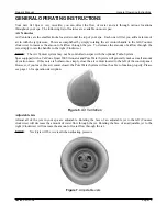
GENERAL OPERATING INSTRUCTIONS
(Continued)
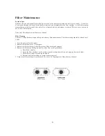
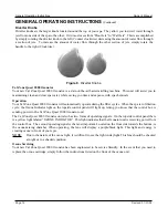
Diverter Knobs
Diverter knobs are the larger knobs located around the top of your spa. They allow you to divert water through
jets from one side of the spa to the other. Or in most cases from “Floor Jets” to” Wall Jets”. This is accomplished
by simply rotating the diverter knob to the left (Counter clockwise) decreasing the amount of water flow through
a section of jets. To increase the amount of water flow through the other section of jets, simply rotate the
handle to the right (Clockwise).
General Operating Instructions
Owner’s Manual
Figure 8
. Diverter Knobs.
Summary of Contents for 1100 Electronic Series
Page 12: ...10 ...
Page 78: ...10 ...
Page 118: ...10 ...
Page 161: ...Owner s Manual Page 11 Electrical Installation Owner s Manual Figure 3 GFCI Hook Up ...
Page 219: ...Owner s Manual Page 11 Electrical Installation Owner s Manual Figure 3 GFCI Hook Up ...
Page 282: ...Owner s Manual Page 11 Electrical Installation Owner s Manual Figure 3 GFCI Hook Up ...


