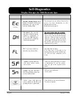
Inadequate water detected in heater.
Inadequate water detected in heater. (Displays
on third occurrence of “dr” message.) Spa is
shut down,
When your spa is first actuated, it will go into
Priming mode.
---F or C
Temperature unknown.
Temperature not current in Economy or Sleep
mode.
Internal problem detected.
Standby Mode has been activated by pressing a
button combination on the user panel.
Safety Suction.
Owner’s Manual
7000 and 9000 Electronic Operation
N
o message on display. Power has been cut off
to the spa.
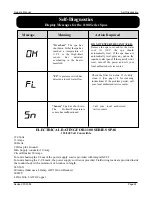
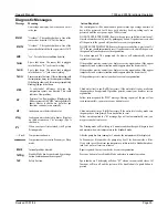
“Overheat” - The spa has shut down. One of the
sensors has detected 118°F at the heater.
“Overheat” - The spa has shut down. One of the
sensors has detected that the spa water is 110°F.
“Ice” - Potential freeze condition detected.
Spa is shut down. The sensor that is plugged
into the Sensor “B” jack is not working.
Spa is shut down. The sensor that is plugged
into the Sensor “A” jack is not working.
Sensors are out of balance. If this is alternating with
the temperature, it may just be a temporary condition.
If the display shows only this message (periodically
blinking), the spa is shut down.
A
substantial difference between the
temperature sensors was detected. This could
indicate a flow problem.
Persistent low flow problems. (Displays on the
fifth occurrence of the “HFL” message within 24
hours.) Heater is shut down, but other spa
functions continue to run normally.
The control panel will be disabled until power returns. Spa settings and time of
day will be preserved for 30 days with a battery back-up; settings only are
preserved until the next power-up on 7000 systems.
DO NOT ENTER THE WATER. Remove the spa cover and allow water to cool.
Once the heater has cooled, reset by pushing any button. If spa does not reset, shut
off the power to the spa and call your dealer or service organization.
DO NOT ENTER THE WATER. Remove the spa cover and allow water to cool. At
107°F, the spa should automatically reset. If spa does not reset, shut off the power to
the spa and call your dealer or service organization.
No action required. The pumps and the blower will automatically activate
regardless of spa status.
If the problem persists, contact your dealer or service organization. (May appear
temporarily in an overheat situation and disappear when the heater cools.)
If the problem persists, contact your dealer or service organization. (May appear
temporarily in an overheat situation and disappear when the heater cools.)
If the problem persists, contact your dealer or service organization.
Check water level in spa. Refill if necessary. If the water level is okay, make sure
the pumps have been primed. If problem persists, contact your dealer or service
organization.
Follow action required for “HFL” message. Heating capacity of the spa will not
reset automatically; you may press any button to reset.
Check water level in spa. Refill if necessary. If the water level is okay, make sure
the pumps have been primed. Press any button to reset.
Follow action required for “dr” message. Spa will not automatically reset; you
may press any button to reset.
The Priming mode will last for up to 4 minutes and then the spa will begin to heat
and maintain the water temperature in the Standard mode.
After the pump has been running for 2 minutes, the temperature will be displayed.
In Economy or Sleep mode, the pump may be off for hours outside a filter.
If you wish to see the current spa temperature, either switch to Standard mode or
turn Jets1 on for at least two minutes.
Repair required. Contact your dealer or service organization.
Press any button to leave Standby Mode and return to normal operation.
Spa is shut down. The display will show “SF” when a vacuum switch closes. All
functions will turn off and the system will be disabled until a panel button is
pressed.
Revised 01/01/04
Page 35
Sns
Snb
Sna
ICE
OHS
OHH
HFL
LF
dr
dry
Pr
BUF
Stby
SF
Diagnostic Messages
Message
Meaning
Action Required
Summary of Contents for 1100 Electronic Series
Page 12: ...10 ...
Page 78: ...10 ...
Page 118: ...10 ...
Page 161: ...Owner s Manual Page 11 Electrical Installation Owner s Manual Figure 3 GFCI Hook Up ...
Page 219: ...Owner s Manual Page 11 Electrical Installation Owner s Manual Figure 3 GFCI Hook Up ...
Page 282: ...Owner s Manual Page 11 Electrical Installation Owner s Manual Figure 3 GFCI Hook Up ...


