Page 6
Revised 01/01/04
QUICK REFERENCE INFORMATION
(Continued)
3.
Filtration Settings and Recommendations:
a. F2= Two hours of filtration every twelve (12) hours. This setting is for occasional spa usage only
b. F4= Four hours of filtration every twelve (12) hours. This setting is for light spa usage. (Up to four hours of usage a week)
c. F6= Six hours of filtration every twelve (12) hours. This setting is for normal spa usage. (Up to six hours of usage a week)
d. F8= Eight hours of filtration every twelve (12) hours. This setting is for heavy spa usage. (Up to eight hours of usage a week)
e. FC= 24 hour filtration. This setting is for spa usage that exceeds twelve hours a week.
NOTE
:
F8 and FC filtration settings are only to be used with spas equipped with the “Spa Cal Filtration Pump”. These setting can
cause conventional two speed pump systems to raise the water temperature well above the set temperature.
4.
To set the filtration cycles, use the following information:
a.
1100 Depress the TEMP pad, followed by the JETS. Each additional press of the TEMP pad will increase the filtration time.
b.
2100 Depress the TEMP pad, followed by the JETS. Each additional press of the TEMP pad will increase the filtration time.
c.
2200 Depress either Up or Down followed by either the JETS 1 or JETS 2. Each additional press of the Up or Down pad will
increase or decrease the filtration time.
d. 2300 Depress either Up or Down followed by either the JETS 1 or JETS 2. Each additional press of the Up or Down pad will
increase or decrease the filtration time.
General Chemical Maintenance Information
(500-Gallon Spa) Start-up:
a.
Add 3 oz. of “Iron Out” or 16 oz. of “Metal Protector”.
b.
Add 2 oz. of “Sodium Bromide”.
c.
Add 2 oz. of “Oxidizer Shock”.
d.
Add 3 to 4 Bromine tablets to a “mostly” closed floater.
NOTE
: Do not place bromine tablets in skimmer basket.
Weekly
1.
Test spa water with test strips for the following items twice a week:
a.
Bromine: Acceptable Range without a Cal Zone Ozonator is between Three (3) to Five (5).
b.
Bromine: Acceptable Range with a Cal Zone Ozonator is between One (1) to Three (3).
c.
Chlorine: Acceptable Range without a Cal Zone Ozonator is between Three (3) to Five (5).
d.
Chlorine: Acceptable Range with a Cal Zone Ozonator is between One (1) to Three (3).
e.
pH acceptable Range is between 7.2 to 7.8 P.P.M.
f.
Alkalinity: Acceptable Range is between 80 to 120 P.P.M.
2.
Add one to two bromine tablets. Usage varies with water temperature and bather loads.
3.
Add 2 oz. of “Oxidizing Shock”. Always follow directions on the container. (Do not use chlorinating shock.)
4.
Add 2 oz. “Stain & Scale Defense” or 3 oz. of “Iron Out” as directed on the container.
5.
Add “pH Up”, if needed. Always follow directions on the container.
6.
Add “Alkalinity Up”, if needed. Always follow directions on the container.
7.
Add “pH Down”, if needed. Always follow directions on the container.
Bi-Weekly
1.
Follow the weekly instructions, and the following.
2.
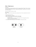
Clean the filter cartridge. (See the “Filter Maintenance” section on pages 13 and 14)
3.
Visually inspect the equipment area for the following:
a. Equipment area is clean. (Cabinet vents are unobstructed)
b. Ozonator operation. (Ozonator only operates during filtration cycles)
c. Pumps, Plumbing, Air Blowers, Unions, Gate valves, and Ozone check valves for leakage.
NOTE
: Component failure as a result of leaks not promptly reported will void the warranty.
I
mportant Chemical Notice:
Before the use of any chemicals, C.A.I. recommends all spa users to consult with their physician for
possible allergic reactions to the corresponding chemicals. C.A.I. also recommends consulting with your
local Cal Spas Dealer for a chemical program that is best suited for your local water condition, climate
and usage habits.
Owner’s Manual
Quick Reference Information
Summary of Contents for 1100 Electronic Series
Page 12: ...10 ...
Page 78: ...10 ...
Page 118: ...10 ...
Page 161: ...Owner s Manual Page 11 Electrical Installation Owner s Manual Figure 3 GFCI Hook Up ...
Page 219: ...Owner s Manual Page 11 Electrical Installation Owner s Manual Figure 3 GFCI Hook Up ...
Page 282: ...Owner s Manual Page 11 Electrical Installation Owner s Manual Figure 3 GFCI Hook Up ...


