Appendix
2005 Spa Owner's Manual
Page 67
8/1/2005
This sensor is delivered inside the control box with temperature sensor, and topside extension loom. Identifying
and connecting the temperature and high limit sensors in the correct location on the circuit board is very
important. Sensors located incorrectly, will cause the spa to operate incorrectly and could result in spa damage.
Identifying and Installation
The temperature sensor has a 3/8” bulb with 50” of wire length, while the high limit sensor has a 1/4” bulb with
48” of wire length. Both of these sensors must be properly installed prior to spa operation.
High Limit Sensor Installation
1.
Locate the high limit sensor plumbing fitting located on the discharge side of pump #1 (Heat Pump).
Note:
The small section of flexible conduit connecting the high limit sensor plumbing fitting to the control box.
2.
Locate the high limit sensor inside the control box.
3.
Firmly press the high limit sensor into the opening inside the control box through the flexible conduit into
the high limit sensor plumbing fitting.
4.
Plug the high limit sensor into the high limit sensor location on the circuit board located inside the control
box. (See the wiring diagram on the inside cover of the control box for proper placement.)
5.
Make sure that both the temperature and high limit sensor are installed correctly according to the wiring
diagram listed on the inside cover of the control box.
Note:
Circuit board programming will not allow spa operation without both sensors being connected to the
circuit board. Verify connections prior to applying power and performing function testing.
Remote Freeze Sensor (Optional)
If you are installing outdoor equipment in cold climate, you should install a Remote Freeze Sensor. This sensor
will protect remote equipment like booster pumps or heater from possible freeze damage.
Sensor Function
When this sensor reaches 40°F it will automatically turn on every pump and blower to circulate water to prevent
freezing. During “Freeze Mode”, the spas functions cannot be controlled. Once the sensor reaches 45°F, the spa
will regain normal operation.
Remote Freeze Sensor Installation
1.
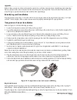
Using a large wire tie strap or zip tie, secure the sensing disk to the booster pump or heater manifold at the
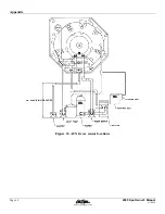
lowest metallic point possible. (See Figure 33 for part identification and installation location)
2.
Plug the other end of the freeze sensor to the “AUX FREEZE” location on the circuit board. (Location may
vary by model. See wiring diagram on the inside cover of the control box)
3.
Using wire tie straps, secure the “AUX FREEZE” sensor wire to the equipment to prevent damage during
maintenance or servicing.
Summary of Contents for LTR20051000
Page 1: ...LTR20051000 Rev E 8 1 2005...
Page 72: ...Appendix Figure 33 AUX freeze sensor locations Page 68 2005 Spa Owner s Manual 8 1 2005...
Page 115: ...Appendix Cal Spas Chemicals 2005 Spa Owner s Manual Page 111 8 1 2005...
Page 117: ......
Page 118: ......
Page 119: ......

