Owner
’s Manual
9000 Electronic Operation
Page 18
Owner’s Manual
Initial Start Up
9000 Electr
onic Control System
One Pump Equipment
When the spa is powered on, it will display configuration digits to let the user know that it will go into Priming
Mode, which can last 4 minutes. (Priming Mode is a self check & can exit at ant time by pressing either Curser.
Initial start up in STANDARD Mode
T
emp Set
(80˚F - 104˚F / 26˚C - 40˚C) (Start-up temperature set @100˚F - 37.5˚C)
The start-up temperature will display after the pump has been running at least 2 minutes. Press either
Cursor
button once to display the set temperature. Press again to increase/decrease to the desired set temperature.
After
3 seconds, the LCD will display the last measured temperature.
Locking the Set-T
emperature
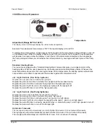
Press either Cursor
, Time, Jets 1, and Cursor within 3 seconds of each other, the panel will display
“TEMPLOCK” confirming the temperature lock.
Locking the Panel
Press
Time, Jets 1 and Cursor within 3 seconds of each other. The panel will display “PANEL LOCK”. All
buttons are frozen except the Time button. To unlock the panel, repeat this step.
T
ime
When time hasn’
t been set, a Time icon flashes. To set time, press Time then “ModeProg” then use the Cursor
buttons to adjust the hours. Repeat this step to set the minutes.
Pr
eset Filter Cycles
Y
ou can preset up to 2 filter cycles a day by programming the start-end times for each cycle. If no cycle is pro-
grammed, the first filter cycle will automatically activate pump #1 from 8AM - 10AM and second filter cycle
activates pump #2 from 8AM - 8PM. Pump Indicator Light will display low speed while operating. The pump
and the ozone generator will run during the filtration cycle. At the start of each filter cycle, the blower will run at
the highest speed for 30 seconds to clean out the air channels. Pump 2 and 3 will run for 5 minutes.Press
T
ime
,
Jets 1
and
Cursor
within 3 seconds of each other
. The panel will display “PANEL LOCK”. All
buttons are frozen except the Time button. To unlock the panel, repeat this step.
Summary of Contents for Pneumatic Series
Page 12: ...10...
Page 78: ...10...
Page 118: ...10...
Page 161: ...Owner s Manual Page 11 Electrical Installation Owner s Manual Figure 3 GFCI Hook Up...
Page 219: ...Owner s Manual Page 11 Electrical Installation Owner s Manual Figure 3 GFCI Hook Up...
Page 282: ...Owner s Manual Page 11 Electrical Installation Owner s Manual Figure 3 GFCI Hook Up...

