EVERSKY
™
MS-CDF-019
–
Manufacturing Nr: 22
0001→
Version B
Update: 2022/06/14
46/70
XVI.5.
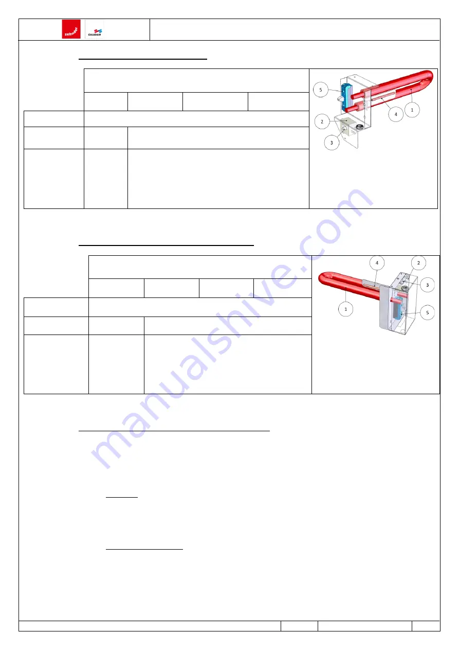
Electrical heating coil (BE)
EVERSKY
(1)
Heating element
(2)
Safety thermal switch THS
(3)
Reset button
(4)
Bulb
(5)
SSR Static relay
500
750
900
1100
Nominal voltage
~1 - 230Vac
–
50Hz
Nominal current
4,3 A
5,4 A
Nominal
power input
1000 W
1250 W
XVI.6.
Electrical frost protection coil (DBE)
EVERSKY
(1)
Heating element
(2)
Safety thermal switch THSD
(3)
Reset button
(4)
Bulb
(5)
SSR Static relay
500
750
900
1100
Nominal voltage
~1 - 230Vac
–
50Hz
Nominal current
4,3 A
5,4 A
Nominal
power input
1000 W
1250 W
XVI.7.
THS and THSD Safety thermal switches
The THS and THSD safety thermostats protect respectively the electrical heating coil and the electrical pre-heating coil (frost
protection) (if equipped) as well as their environment close to any excessive overheating in the event of, for example, a failure of a
control device (contactor, static relay, controller...) or the supply fan.
XVI.7.a.
Location
The THS safety thermostat is located on the support plate of the heating element see XVI.5 Electrical heating coil (BE).
The THSD safety thermostat is located on the support plate of the heating element see XVI.6 Electrical frost protection coil (
XVI.7.b.
Electrical connection
The THS and THSD safety thermostats are of the NC (Normally Closed) type. The contact opens when the bulb temperature exceeds
90°C (not adjustable). The electrical connection is made between the terminals (C) and (2) according to the electrical diagram see
XVII GENERAL WIRING DIAGRAM.


