background image


ITC 220 Base Station Transceiver Installation Guide PN 133991 Rev. A

 | Page 35 

C.2 GPS ANTENNA PLANNING CONSIDERATIONS 

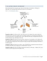
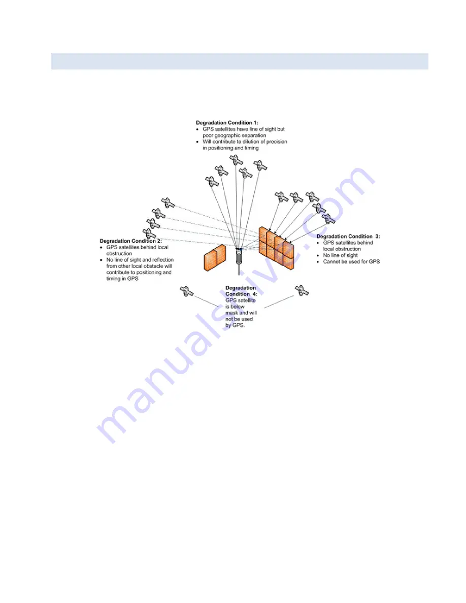
When determining GPS antenna locations, several factors should be taken into consideration. Following is an 
explanation of four typical degradation conditions that may occur for GPS antennas. 

Figure 16 — GPS antenna degradation conditions 


Degradation condition 1:

 The GPS antenna has a direct view of some of the satellites as they move and fall behind 

various obstructions. There may be instances where the satellite constellation can provide replacement satellites that 
are unobstructed. However in the example shown, even the visible GPS satellites have poor geographic separation and 
this will contribute to a poor DOP (Dilution of Precision). 

Degradation condition 2:

 The GPS antenna may only have an indirect view of some satellites, so that a reflected path 

that is longer than the direct path is all that is available. This will result in an artificially long path, and timing errors will 
be introduced, likely causing position errors during the self-survey and timing anomalies, depending on the distance of 
the reflecting object. 

Degradation condition 3:

 The GPS antenna will have no view of Satellites that are completely obstructed and they will 

be invisible to the antenna, even though they are in the GPS Almanac in the radio. 

Degradation condition 4:

 The GPS radio will ignore satellites that are below the mask angle ( ~ 10 degrees) that is set in 

the radio, even if the antenna has perfect visibility of them. 


Summary of Contents for ITC 220

Page 1: ...ITC 220 Base Station Transceiver HIGH PERFORMANCE WIRELESS FOR RAILROAD PTC Installation Guide PN 133991 Rev A Revised July 2012 ...

Page 2: ...REVISION HISTORY REV DATE REVISION DETAILS A July 2012 Initial release Part number 133991 ...

Page 3: ...e and Wayside Transceiver units must be professionally installed and must ensure a minimum separation distance between the antenna or radiating structure and any person Refer to Table 1 and 2 on pages 3 and 4 of the RF Energy Exposure Guide for ITC 220 Base Station Locomotive and Wayside Transceivers Installed in Vehicles or at Fixed Sites for recommended minimum lateral distance as applicable for...

Page 4: ... 5 Equipment Modifications 8 4 Base Transmitter Operation 9 4 1 Base Station Transceiver Channelization And Frequency Range 9 4 2 Base Channel Restrictions 9 4 3 Base Radiated Power Limits 9 5 Routine Maintenance 10 6 Installation 11 6 1 Required Equipment 12 6 2 Unpack and Inspect the Unit 13 6 3 Confirm SD Memory Card CIM is Installed and Seated 13 6 4 Mount the Base Station Transceiver 13 6 5 G...

Page 5: ...iew 34 C 2 GPS Antenna Planning Considerations 35 C 2 1 Minimize Potential of GPS Antenna Issues 36 C 2 2 Determine GPS Coordinates 36 APPENDIX D Configure the Computer Ethernet Ports to Communicate with the Transceiver 39 D 1 To Configure the Computer Ethernet 1 Interface for Communication with the Transceiver MAINT Port 40 D 2 To Configure the Computer Ethernet 2 Interface for Communication with...

Page 6: ...t 67 I 3 2 Diversity RX2 Receiver Measurement 68 I 3 3 Alternate TX RX Receiver Measurement 68 I 4 Put a Trace on a Feature 69 APPENDIX J Managing Software Application Images 72 J 1 Determining Software Image Status 72 J 2 Updating Software Images 74 J 2 1 Updating Transceiver Software Using the Command Line 74 J 3 Rolling Back an Image 78 J 3 1 How Automatic Rollback Occurs 78 J 3 2 Determining I...

Page 7: ... over speed derailments movement of a train through a switch left in the wrong position and incursion of trains into maintenance of way work limits Interoperable Train Control ITC defines industry standard messaging and communication protocols that support PTC and ensure interoperability between components CalAmp s line of ITC 220 Radio Transceivers for locomotive base station and wayside applicat...

Page 8: ...change without notice General Frequency Range 217 6 222 0 MHz Channel Spacing 25 kHz Temperature Range Operating 30 C to 70 C Storage 55 C to 85 C Operating Humidity 0 95 non condensing Frequency Stability 0 1 ppm over operating temperature range DC Input Voltage Range 48 V model 42 54 VDC Damage limit 60 VDC 24 V model 21 27 VDC Damage limit 30 VDC DC Current Drain 48 V model Transmit 6 A peak ma...

Page 9: ...ted channels Modulation Designators 16 kbps 8K90DXW 32 kbps 17K8DXW Conducted Spurious Emissions 25 dBm max Max Duty Cycle Rating 50 Receiver Maximum Usable Sensitivity Static BER 10 4 16 kbps 111 dBm 32 kbps 108 dBm Adjacent Channel Selectivity 70 dB at 25 kHz offset Spurious Response Rejection 70 dB Intermodulation Response Rejection 65 dB Blocking 1 MHz offset 80 dB Number of Simultaneous Recei...

Page 10: ...perature range and provide worry free operation 1 3 1 DIMENSIONS Overall dimensions of the ITC 220 Base Station Transceiver are 19 15 in width 17 74 in depth 6 96 in 4U height as shown in Figure 1 which follows Figure 1 ITC 220 Base Station Transceiver overall dimensions Dimensions shown are in inches Reconfigurable mounting brackets allow the Base Station Transceiver to be front mounted or mid mo...

Page 11: ... of the Base Station Transceiver 1 3 2 1 FRONT PANEL The following figure and table illustrate the interface connections on the front panel Figure 3 Base Station Transceiver front panel interface connections Table 1 Base Station Transceiver front panel interface connections Interface Connector Type Label Maintenance Ethernet RJ 45 MAINT CIM socket SD memory card receptacle CIM ...

Page 12: ...enna Type N female RX2 GPS Antenna TNC female GPS DC Power Input Threaded posts studs for ring lug connection 24 VDC or 48 VDC Data Network Ethernet RJ 45 LAN Ground connection Threaded post stud for ring lug connection 1 4 RELATED DOCUMENTS Other documents related to this ITC 220 Base Station Transceiver Installation Guide include ITC 220 Locomotive Transceiver Installation Guide CalAmp PN 133971...

Page 13: ...s packaged with each Base Station and Locomotive Transceiver and available online or by request for specific information regarding safe distances that must be maintained between personnel and energized transmitting antennas The information in the RF Energy Exposure Guide for ITC 220 Base Station Locomotive and Wayside Transceivers Installed in Vehicles or at Fixed Sites RF Energy Exposure Guide is...

Page 14: ...he RF Energy Exposure Guide Unauthorized antennas equipment modifications or attachments could invalidate any equipment warranty or authority to transmit Modification could damage the radio transceiver and may violate FCC or IC regulations Contact CalAmp before using other antennas 3 4 RF INTERFERENCE TO RESIDENTIAL RECEIVERS Notice to user This device complies with Part 15 of the FCC Rules Operat...

Page 15: ...a height specified in 47CFR Subpart T 90 701 et seq or Industry Canada SRSP 512 6 3 as applicable Important The following supplementary antenna system information discusses means for the licensee to determine effective radiated power ERP and to comply with regulatory power limits Licensees must comply with specific power vs HAAT limitations for fixed base stations unless operating under an explici...

Page 16: ...wer limit is less than the minimum Base rated power of 10W PEP 40 dBm PEP then an external RF attenuator would be inserted in the feed line to increase the loss between transmitter and antenna to achieve compliance 5 ROUTINE MAINTENANCE The Base Station Transceiver requires the following routine maintenance Remove dust and obstructions from heat sink fins Ensure that the unit is not subjected to e...

Page 17: ...on 6 3 3 Mount the unit section 6 4 4 Ground the unit section 6 5 5 Install current limiting protection section 6 6 6 Connect the narrowband RF antennas section 6 7 7 Connect the GPS antenna section 6 8 8 Connect the Ethernet cable section 6 9 9 Connect the power cable section 6 10 10 Power on the unit section 6 11 At the conclusion of installation you will verify that the Base Station Transceiver...

Page 18: ...e frequency adjustments require frequency standard accuracy to 0 01 ppm or better 60 dB power attenuator load Consists of two pieces with 100 W and 2 W min power rating Constant voltage DC power supply Verify unit supports voltage and current draw required by unit under test Host computer with at least one Ethernet port and XtermW or equivalent terminal program installed If the host computer s Eth...

Page 19: ... inserted in the orientation shown on the door To confirm the CIM card is installed and seated Open the CIM door to ensure the SD memory card is present in the CIM socket Push the SD memory card once to release it Push the SD memory card again to ensure it is seated in the socket Once confirmed close and secure the CIM door Figure 5 CIM card door on a Base Station Transceiver 6 4 MOUNT THE BASE ST...

Page 20: ...ceiver chassis See the following table for details about which screws are partnered with each bracket and with the dust cover Table 4 Mounting brackets dust cover and partnered mounting screws Description Appearance Partnered fastener description Quantity Left bracket Machine screw 8 32 3 8 Flat head Phillips stainless steel 5 screws Unused mounting location No image Machine screw 8 32 3 8 Pan hea...

Page 21: ...20 Base Station Transceiver Installation Guide PN 133991 Rev A Page 15 Figure 6 Base Station Transceiver in 19 inch rack mount Figure 7 Channel rack installation with mounting brackets in mid plane position ...

Page 22: ...that Equipment that produces substantial heat is not installed below the Base Station Transceiver Each unit is secured with four screws on each side There is adequate space to access the CIM SD memory card There is adequate space for cable connections The unit is resting on a vented cabinet shelf Cables are restrained to prevent kinking and stressing connectors 6 5 GROUND THE RADIO TRANSCEIVER CHA...

Page 23: ... operational ranges and damage limits for each version Table 5 Base Transceiver input power parameters with operational ranges and damage limits Parameter 24 VDC version 48 VDC version Nominal DC Power Input Voltage 24 VDC 48 VDC Operational range 21 27 VDC 12 5 42 54 VDC 12 5 Damage limit 30 VDC 60 VDC 6 7 CONNECT RF ANTENNAS 6 7 1 ANTENNA PLANNING Antenna planning for each site takes place befor...

Page 24: ... the radio GPS receiver low noise amplifier Combinations of strong interferers could mix and interfere directly with the GPS signal quality Test the transceiver GPS with any interference source active to qualify the antenna antenna isolation of the GPS antenna position See APPENDIX C GPS Satellite Constellation Overview and Antenna Planning Considerations if necessary for reference Because GPS sat...

Page 25: ...inch studs marked and to connect the 10 AWG power cables The power connectors are threaded posts for ring lug terminals and are located on the rear panel of the unit Figure 11 Power connector studs on the rear panel of the Base Station Transceiver The power connectors are threaded posts for ring lug terminals and are located on the rear of the unit Important The transceiver does not have a power s...

Page 26: ... plant To connect the power cable 1 The Base Station Transceiver does not have a power switch Verify that the power is off before connecting the unit to a power source 2 Run power cables into the rack and route them through the rack to the rear of the unit 3 Remove the outer nut on both studs 4 Place the lock washers over the inner nut on both studs 5 Place the ring lugs of the power cable onto th...

Page 27: ...off and on repeatedly within four minutes of powering it on Subjecting the transceiver to three or more successive power cycles within four minutes can cause a reboot error If a reboot error occurs remove power replace the SD card and then apply power and allow the transceiver to boot up normally without power interruptions 6 11 1 LED DIAGNOSTICS A blinking PWR Power LED on the front panel indicat...

Page 28: ...in 25 of the RF output power setting The CIM script file is not present or has invalid or corrupt data If the Fault LED illuminates a time stamped entry will display in XtermW specifying the cause Red 6 11 2 REVIEW THE POWER ON SELF TEST POST RESULTS A POST is a series of several dozen tests that the transceiver quickly runs on itself each time it boots up to determine if it has a problem or is mi...

Page 29: ... Click Send click Command and then type COMMISSION 4 Click OK The transceiver will return a Commission status of either Radio State COMMISSIONED or Radio State UNCOMMISSIONED If the transceiver returns a status of Radio State COMMISSIONED the transceiver has been commissioned and you can continue on to the next step Verify LAN Ethernet Port is Operational If the transceiver returns a status of Rad...

Page 30: ...ere is an SD card installed and seated that contains a valid CIM script file Without an SD card present and without a valid CIM script the transceiver will not transmit and will continually reboot every few minutes Check the LEDs Use the LEDs to determine the state of the system and whether there is a fault condition See LED Diagnostics for more information A time stamped entry will display in Xte...

Page 31: ...cable 7 Replace the transceiver When replacing a transceiver if the SD card contains a valid CIM script remove the SD memory card from the nonworking transceiver and insert and seat it in the replacement transceiver The replacement transceiver will use the CIM script on the SD memory card and its configuration will be the same as the original transceiver 7 3 SD MEMORY CARD PROBLEMS SD memory card ...

Page 32: ... breaks 3 Check the cable connector and radio connector for corrosion 4 Issue the diagnostic command STAT to verify the VSWR and power output of the last transmission 5 Check cable continuity 6 Replace the cable or connector 7 Replace the antenna 8 Check the radio output power without the antenna connected 9 View the Standing Wave Ratio measurements At the XtermW prompt type VSWR and press Enter T...

Page 33: ... FALSE Transmitter State Available 5 Inspect the SD memory card to ensure it is seated properly in the CIM socket in the orientation shown and is not damaged 6 Make sure there is a valid CIM script file loaded from the SD card At the XtermW prompt enter INICHECK SCRIPT 7 Make sure the antenna cable connectors are securely connected to the antenna and to the radio connectors 8 Adjust the power outp...

Page 34: ...and transceiver connector for corrosion 6 Replace the cable or connector 7 Check the antenna for any defects or breaks 8 Replace the transceiver When replacing a transceiver if the SD card contains a valid CIM script remove the SD memory card from the nonworking transceiver and insert and seat it in the replacement transceiver The replacement transceiver will use the CIM script on the SD memory ca...

Page 35: ...BLEMS When the RF Link LED illuminates it means that the Base Station transceiver is connected to one or more Locomotive or Wayside transceivers When the LED is off it means that the Base Station transceiver is not currently connected to a Locomotive or Wayside transceiver Problem indicators The RF Link LED is off To troubleshoot RF link issues 1 Make sure the transceiver is turned on and the gree...

Page 36: ...Short Tx 0 Rx 0 BcastLoc Tx 0 Rx 0 BcastComm Tx 0 Rx 0 UniLocal Tx 2 Rx 4 UniLocal Ak 2 UniCommon Tx 0 Rx 0 UniCommon Ak 0 UniBdcst Tx 0 Rx 0 OtherLocal Tx 0 Rx 0 OtherLocal Ak 0 OtherComm Tx 0 Rx 0 OtherComm Ak 0 Illegal Rx 0 Messages Tx 2 Rx 2 8 Replace the transceiver When replacing a transceiver if the SD card contains a valid CIM script remove the SD memory card from the nonworking transceive...

Page 37: ...Industries Alliance EIRP Equivalent Isotropically Radiated Power ERP Effective Radiated Power EVM Error Vector Magnitude FCC Federal Communications Commission U S FRA Federal Railroad Administration U S FTDMA Fixed Time Division Multiple Access GPS Global Positioning System HAAT Height Above Average Terrain IC Industry Canada ITC Interoperable Train Control ITCR Interoperable Train Control Radio k...

Page 38: ... SD memory card Secure Digital memory card SMA connector SubMiniature version A connector SRSP Standard Radio System Plan Canada TCP IP Transmission Control Protocol Internet Protocol TNC connector Threaded Neill Concelman connector TX Transmit U Unit measure of height for rack mounted equipment defined 44 5 mm approximately 1 in for rack mounted equipment that conforms to EIA 19 inch rack standar...

Page 39: ...h with 50 Ohm termination Two antenna configuration One antenna is connected to the primary receive port which is the TX RX port A second antenna is connected to the diversity port RX2 Terminate the remaining port RX1 which is unused with 50 Ohm termination Three antenna configuration One antenna is connected to the primary receive port which in this configuration is RX1 A second antenna is connec...

Page 40: ...nation of 55 degrees at an altitude of 20 200 km Figure 15 GPS satellite constellation This type of satellite is referred to as an MEO Medium Earth Orbit satellite They are not in geostationary orbit This is important because unlike GEO Geostationary Earth Orbit satellites which are located at an altitude of 37 790 km over the equator MEO satellites move throughout most of the sky so there is no s...

Page 41: ...tes have poor geographic separation and this will contribute to a poor DOP Dilution of Precision Degradation condition 2 The GPS antenna may only have an indirect view of some satellites so that a reflected path that is longer than the direct path is all that is available This will result in an artificially long path and timing errors will be introduced likely causing position errors during the se...

Page 42: ...and important case of configuration that does not fit neatly into any category It is an installation procedure that affects configuration Base Station and Wayside Transmitters are equipped with internal GPS receivers The GPS provides the precision timing required to synchronize the network Configure the GPS to use timing mode since it provides the most precise and reliable timing possible In timin...

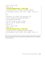
Page 43: ...o cannot obtain the timing needed to allow precision transmissions without the survey completing The survey has to be repeated whenever the transceiver or GPS receiver is swapped out Use the POS command to request the radio to survey its own position In the following example POS TIMING SURVEY 1 1 requests the GPS to survey its own position for at least one minute until it detects an rms error of 1...

Page 44: ... Position entered from GPS survey Precision LOW NSAT 11 HDOP OFF 99 99 HOLD OFF LOCK OFF DGPS Age 99 Seconds COPY Port OFF SCALE rrc values 0 0000 RXDIFF ON All Timing mode Requested TIMING Actual TIMING Surveyed ECEF position x 230367629 y 365342370 z 467746792 Survey parameters fixed err 993928 req err 1000000 req time 60 Because it may take several minutes for the survey to complete and complet...

Page 45: ...annot be obtained then contact your network administrator for instructions If you are using the factory defaults then use the following examples If you are not using the factory defaults then contact your network administrator for the appropriate IP settings For these examples Ethernet 1 refers to the computer s first Ethernet port and is used for communication with the transceiver MAINT port and ...

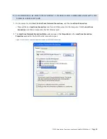
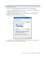
Page 46: ...ions and then Local Area Connection There will be one Local Area Connection icon for each Ethernet port on the computer Click the Local Area Connection icon that corresponds to the first Ethernet port 2 The Local Area Network Connection Status window opens Click Properties and the Local Area Connection Properties window for the first Ethernet connection opens Figure 17 Local Area Connection Proper...

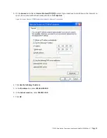
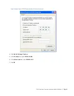
Page 47: ...elect it you may have to scroll down in the items list to see it do not remove the check mark and then click Properties Figure 18 Internet Protocol TCPIP Properties Window for Ethernet 1 connection 4 Click Use the following IP address 5 In the IP address box enter 192 168 255 200 6 In the Subnet mask box enter 255 255 255 0 7 Click OK ...

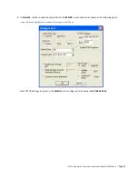
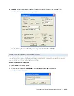
Page 48: ...ge 42 8 In XtermW set the connection properties for the MAINT port connection as shown in the following figure Figure 19 XtermW Configure Port window with settings for MAINT port Note TCP IP Settings for Host on the MAINT port is configured for IP address 192 168 255 201 ...

Page 49: ...Ethernet port on the computer Click the Local Area Connection icon that corresponds to the second Ethernet port 2 The Local Area Network Connection Status window opens Click Properties and the Local Area Connection Properties window for the second Ethernet connection opens Figure 20 Local Area Connection Properties window for Ethernet 2 connection 3 On the General tab click on Internet Protocol TC...

Page 50: ... Guide PN 133991 Rev A Page 44 Figure 21 Internet Protocol TCP IP Properties window for Ethernet 2 connection 4 Click Use the following IP address 5 In the IP address box enter 10 255 255 200 6 In the Subnet mask box enter 255 255 255 0 7 Click OK ...

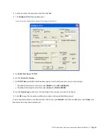
Page 51: ...the LAN port is configured for IP address 10 255 255 201 D 3 CREATING AN XTERMW CONNECTION PROFILE A connection profile is a group of configuration settings created in XtermW and saved to use again for convenience when connecting to an Ethernet port using the same settings To create an XtermW connection profile 1 Open XtermW if it is not already open 2 From the File menu select New Connection and ...

Page 52: ...e IP address and port for the Ethernet port you are connecting to The default IP address for the Transceiver MAINT port is 192 168 255 201 The default IP address for the Transceiver LAN port is 10 255 255 201 8 Set the Device Type and the rest of the settings in the window as shown in the figure 9 Click OK to save the connection profile and connect to the specified Ethernet port To use a previousl...

Page 53: ...OST DDR Data Line Test PASS HOST SPI PASS HOST SDCARD Present PASS HOST SDCARD Fail Pin PASS HOST SDCARD Write Protect OFF HOST SDCARD Access PASS HOST I2C Controller PASS HOST I2C Mux PASS HOST RTC PASS HOST BOOT FLASH C PASS HOST BOOT FLASH D PASS HOST DATA FLASH E PASS HOST SEEPROM STAMP PASS HOST CALIBRATION PARAMETERS PASS HOST REG PARAMETERS PASS HOST ID PARAMETERS PASS HOST CHANNEL TABLE PA...

Page 54: ... MCASP PASS DSP PSC PASS DSP EXTERNAL CLOCK PASS DSP IQ MIXER PASS DSP RX ADC PASS DSP TX NULL ADC PASS DSP DDS PASS FPGA MEMORY PASS FPGA Clocks PASS FPGA Tx PASS HOST 28 0v Supply PASS 28 915 HOST 11 5v Supply PASS 11 432 HOST 5 0v Supply PASS 5 022 HOST 3 3v Supply PASS 3 277 HOST 2 5v Supply PASS 2 490 HOST 1 8v Supply Host PASS 1 808 HOST 1 8v Supply DSP PASS 1 814 HOST 1 5v Supply PASS 1 396...

Page 55: ...OST PA Temp PASS 32 200 HOST Driver Temp PASS 32 200 HOST PA Current PASS 0 000 HOST Driver Current PASS 0 000 boot loader version 0 22 1 SVN 17525 2011 07 29 reset_count 3 active_index 2 active_source Flash1 active_user USER_BOOT Inx Pri Stat Fail Lnch Name Notes Last Status 2 42 RDY 1 2 D 01011506 A14 ACTV Success ...

Page 56: ...reamble bits using the numeric keypad 1111 0011 0011 0111 1110 1110 1011 0110 0011 0111 0110 0110 0000 0110 0111 0010 12 Insert a PN9 sequence at the end of the preamble sequence INSERT 13 Select INSERT PN9 Insert PN9 14 Choose Insert PN9 not Seed 1FF Insert PN9 15 Add a post to the end of the sequence Using the cursor keys arrows navigate the cursor to the end of the sequence just inserted Arrow ...

Page 57: ...Mode Setup to define additional parameters Mode Setup 31 Load the user defined data file just created Data 32 Pick User File User File 33 Use cursor keys to select DQPSK and press Select File Select File 34 Set Custom to On Custom 35 Save the file Save 36 Select a register that is not in use Select Reg and then 1 or suitable unused register and then Save Reg 37 Press Preset and now load the wavefo...

Page 58: ... a custom user file User File 10 Create a user file Create File 11 Define the preamble bits using the numeric keypad 1111 0011 0011 0111 1110 1110 1011 0110 0011 0111 0110 0110 0000 0110 0111 0010 12 Insert L1 Header bits using the keypad 1000 0110 1101 0011 1001 1100 1101 1111 1100 10010010 1100 13 Insert an FEC encoded PN9 sequence at the end of the header sequence 1111 1111 1100 0110 1000 1010 ...

Page 59: ...numeric keypad to enter 0 35 then Enter 0 35 Enter 25 Return to an upper level by pressing Mode Setup to define additional parameters Mode Setup 26 Select Symbol Rate Symbol Rate 27 Using the numeric keypad enter 16 ksps for full rate testing or 8 ksps for half rate testing 16ksps 8ksps 28 Return to an upper level by pressing Mode Setup to define additional parameters Mode Setup 29 Load the user d...

Page 60: ...lect GPS GPS 4 Select Real Time MSGPS Real Time MSGPS 5 Select Scenario Scenario 6 Using arrow keys highlight either Hawaii or SantaRosa Arrow keys 7 Select Scenario Select Scenario 8 Select number of satellites 8 Number of Satellites 9 Select More to return to main GPS page More 10 Select More More 11 Verify GPS Ref f0 1 023 Mcps GPS Ref f0 12 Verify GPS Ref Clk INT GPS Ref Clk 13 Verify IQ Phase...

Page 61: ...booted up successfully executing the CIM script A computer with Ethernet interfaces configured to communicate with the transceiver is connected to the transceiver MAINT port The XtermW program is installed and running on the computer You have permission to enter commands that can change the configuration settings You can enter some commands that allow you to get the transceiver s operational statu...

Page 62: ...our password from the default or a password you have been using to a new password is a good way to improve security on the transceiver If you are not sure when to change your password check with your company s established security procedures The requirements for a password are Passwords can consist of any alphanumeric characters a b c 1 2 3 plus the dash character in any combination For example a ...

Page 63: ...T YOUR PASSWORD To recover from a forgotten password Ask an administrator who has permission to reset users passwords to the default password to reset your password to the default Change your password from the default password to your own password See G 3 Change Your Transceiver Password ...

Page 64: ...er is invalidated The transceiver is reconfigured at startup if a CIM is found and the configuration is invalid INICHECK allows a user to check the configuration manually at any time Syntax INICHECK or INICHECK script Returns OK on success or Bad Parameter on failure LINKSTAT The LINKSTAT command displays link statistics by link On a remote transceiver locomotive or wayside it also shows which Bas...

Page 65: ...SVN 17525 2011 07 29 H W Base Board ITC Role Base The software revision is highlighted above and is 01 01 15 06 in this example STAT RF The STAT RF command displays the total number of packets transmitted and received over the air by the radio Statistics are broken down by packet type There are also several running totals included stat rf 19 28 54 282 Bytes Tx 33213 Rx 191 Segments Tx 4 Rx 4 Corr ...

Page 66: ...r by radio stat hrx 19 15 19 793 HRX STATISTICS TX RX Bytes 24 78 Messages 2 2 Service Msgs 2 1 Data Messages 0 1 Short Broadcast 0 0 Long Broadcast 0 0 Unicast 0 0 SH Code 0 0 0 SH Code 1 0 0 SH Code 2 0 0 SH Code 3 0 0 SH Code 4 0 0 SH Code 5 0 0 SH Code 6 0 0 SH Code 7 0 0 SH Code 8 0 0 SH Code 9 0 0 SH Code 10 0 0 SH Code 11 0 0 SH Code 12 0 0 SH Code 13 0 0 SH Code 14 0 0 SH Code 15 0 0 Unkno...

Page 67: ...on Transceiver can cause damage Confirm the voltage rating of the Transceiver and power source before applying power Table 10 Base Transceiver input power parameters Parameter 24 VDC version 48 VDC version Nominal DC Power Input Voltage 24 VDC 48 VDC Operational range 21 27 VDC 12 5 42 54 VDC 12 5 Damage limit 30 VDC 60 VDC Current draw while transmitting rated power 7 5 A typical while transmitti...

Page 68: ...d adjustment setup Configure the Agilent E4417A power meter Use these settings Select Channel Sensor Mode Normal Range Auto Filter Auto Duty Cycle Off Offset On Use offset from cable and attenuator Frequency 221 137 MHz CF Table Off FDO Table Off Video Avg Off Video B W Low Step Detect On Gates Gate Start 3 ms Gate Length 97 ms Trace Setup Start 1 ms Length 99 ms Trigger Cont Trig Measure Setup ...

Page 69: ...rmat Using the commands below in XtermW key up the transmitter at either π 4DQPSK full or half rate and observe radio performance To key up transmitter at π 4DQPSK full rate 1 In XtermW type the following commands STOP SCHED DEL ALL DSP_MODE IDLE DSP_MODE TEST L1_TEST SET TXFREQ value L1_TEST SET TXMOD DQPSK L1_TXDUTY 1000 300 0 where value equals the desired frequency of operation Note The ratio ...

Page 70: ...sired frequency of operation Note The ratio of 300 1000 denotes a 30 transmit duty cycle 2 Once observation of radio performance is complete turn off transmit operations by typing L1_TEST STOP Note Each figure in this section shows a typical transmission spectrum or power measurement of a locomotive radio Figure 26 Typical transmission spectrum DQPSK ...

Page 71: ...ry If additional tuning is required use the TXPOWER command to increase or decrease output power relative to the current power level Notes You cannot adjust power above the factory calibrated setting π 4DQPSK is a linear modulation technique To adjust RF output power 1 Key up the transmitter for full rate π 4DQPSK modulation using the following commands in XtermW STOP SCHED DEL ALL DSP_MODE IDLE D...

Page 72: ...you must save the setting The procedure will vary depending on whether or not the FACTORY DEFAULT INIT command is included in the CIM file Note If you do not know if the FACTORY DEFAULT INIT command is included in the CIM file then contact your network administrator If the FACTORY DEFAULT INIT command is not set in the CIM In XtermW type SAVE This will result in a change sustained across power cyc...

Page 73: ... PEP 10 to 75 W PEP 7 5 W PEP is 38 7 dBm peak Average power would be about 3 dB less The base range of 10 to 75 W is less than a 9 dB range I 3 MEASURE FULL RATE RECEIVER SENSITIVITY I 3 1 PRIMARY RX1 RECEIVER MEASUREMENT To begin the test make sure the E4438C signal generator is outputting the proper wave form into the RX1 port on the transceiver Next issue the following commands in XtermW STOP ...

Page 74: ...P_CMD SET BER RAW L1_TEST START RX DSP_CMD BAC 2 SCHED I 6 L1_TEST GET ERRCOUNTS 3 3 where value equals the desired frequency of operation Once observation of radio performance is complete turn off transmit operations by typing L1_TEST STOP I 3 3 ALTERNATE TX RX RECEIVER MEASUREMENT To begin the test make sure the E4438C signal generator is outputting the proper wave form into the TXRX port on the...

Page 75: ...ble trace features Feature Description of traced data and notes 0 16 All activity on a selected I O port CLASC Class C time and location messages CLASD Information about Class D messages DEBUG Variety of diagnostic data on ITC RADIO activity DLOG Replaces DSP_CMD LOG on off and displays the DSP status log DSP Trace messages transferred from the DSP via the HPI interface ETH Information about the E...

Page 76: ...d and then type TRACE port maint where TRACE is the trace command port is a subcommand and maint refers to the MAINT port 5 Click OK 6 Select the trace feature and output destination Click Send click Command and then type TRACE level feature destination where TRACE is the trace command level is a number from 0 to 7 feature is the name of the feature you want to trace and destination is the locatio...

Page 77: ...ITC 220 Base Station Transceiver Installation Guide PN 133991 Rev A Page 71 To stop a trace 1 In XtermW click Send click Command and then type TRACE OFF 2 Click OK ...

Page 78: ...ins how to Obtain software image status information Update transceiver software application images Perform a manual software rollback Determine if automatic roll back has occurred Maintain multiple software images in the radio J 1 DETERMINING SOFTWARE IMAGE STATUS The APPS command displays a report containing the BootInfo information and a table of all installed application images The BootInfo inc...

Page 79: ... times APPS 04 09 12 23 34 20 BEGIN BOOTINFO INFORMATION tag_id 3 length 254 version 0 22 1 SVN 17525 2 1011 07 29 reset_count 11 active_index 2 active_source Flash1 active_user USER_APP schedule enable ON schedule status BLANK schedule index 256 schedule sched 256 00 2255 00 00 END BOOTINFO INFORMATION Inx Pri Stat Fail Lnch Date Time Size Name Notes Last Status 2 27 RDY 0 2 04 09 2012 05 10 PM 3...

Page 80: ... display a list of all installed application images 3 Ensure that there is adequate space available on the non active drive to store the file If not delete an unneeded image from the non active drive using the APPS DELETE command If the image to be deleted is RDY or NRDY it must first be declared invalid using the APPS INVALIDATE command 4 Establish a connection from XtermW to the transceiver usin...

Page 81: ... treated as case insensitive 9 To select this image immediately after it is downloaded select the Select check box When you select the Select check box XtermW automatically executes the APPS SELECT image file command after the software image is downloaded It also causes XtermW to enable the Boot check box The Boot check box is available only when you select the Select check box When you select the...

Page 82: ...r Installation Guide PN 133991 Rev A Page 76 When you select the Schedule check box XtermW automatically executes the APPS SCHED date time image file command after the software image is downloaded 11 Click Send to begin the download ...

Page 83: ...mage will be listed as ACTV active image after the reboot If the Select check box was cleared the downloaded software image will be listed with the status of NRDY If the Select check box was selected the downloaded software image will be listed in the top row of the Apps table with the highest priority and a status of RDY If the Schedule check box was selected the downloaded software image will be...

Page 84: ...e image Automatic rollback has occurred The previous image will display a FLTY status in the Apps report Else if no other RDY status images are found then a Update the failure counter of the current active image even if the failure counter exceeds the failure counter threshold b Keep the current active image as RDY c Retry launching the current active image J 3 2 DETERMINING IF AUTOMATIC ROLLBACK ...

Page 85: ... PM 3364220 C 01011503 A18 ACTV Success 2 26 RDY 0 2 04 09 2012 05 05 PM 3361028 D 01011401 A18 Success 1 25 RDY 0 0 04 09 2012 05 03 PM 3346860 C 01011203 A18 If required setup a CIM script association for each image to ensure that the proper CIM script executes when a particular image becomes the active image Use the INISELECT command To manually roll back to D 01011401 A18 use the following com...

Page 86: ...DY and NIV are selectable Schedule SCHD Only images with status of RDY or NRDY are eligible for scheduling Unschedule NRDY Images with the status of SCHD may be unscheduled with the APPS UNSCHED command Demote RDY Priority value swapped with next lower priority image with a RDY status Only images with a RDY status may be demoted Deselect NRDY Image is excluded from selection by the automatic rollb...

Page 87: ... priority exceeds the threshold and there exists other RDY images the automatic rollback algorithm changes the status of the image to FLTY causing the next highest priority RDY image to become the active image Status change from SCHD to RDY with highest priority If APPS SCHED is enabled and a schedule has expired the transceiver will automatically select the scheduled image Delete image If an APPS...

Page 88: ...ctive high quality solutions to a broad array of customers and end markets CalAmp is the leading supplier of Direct Broadcast Satellite DBS outdoor customer premise equipment to the U S satellite television market The Company also provides wireless data communication solutions for the telemetry and asset tracking markets private wireless networks railroad Positive Train Control PTC radio transceiv...

Reviews: