background image

SECTION 7 


um_tslm rev3.doc 

Page 37 of 62  


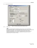
After radio parameters are selected, click the OK button to store the information into  


the PC’s memory. To load parameters into the TSLM, initiate a Program from the Edit menu 

or select the Program icon from the Tool Bar. After the programmable parameters are 
loaded into the TSLM, save the parameter information using the Save Data As option in the 

File pull-down menu. The name and location of the file (*.dat extension) will appear on the 
status bar at the bottom of the screen. The ID number of the radio will automatically 

increment by one when the connected radio has completed its programming in order to 
facilitate programming multiple radios. Take care to avoid multiple clicks on the “OK” button 
during the programming operation. Clicking “Cancel” and re-clicking the “Program” icon will 

allow another programming operation without changing the ID of the radio. 

7.2.4  Read Programmable Settings Settings 


The Read Programmable Settings command will read parameters from the current 

TSLM and store the information in local memory. The parameters can be viewed and/or   
edited with the Setup TSLM Parameters screens. 
 

Note: CalAmp DataCom recommends a Read be done anytime an initial connection is made  
to the TSLM Setup Port before accessing the Setup TSLM Parameters screen. This will help  

the user avoid writing erroneous parameters to the connected unit. Take note of the unit ID 
number being programmed. This ID number will be used to create a diagnostic ID List.                    


7.2.5 Port 

Settings 

 
TSLM programming is completed through the PC’s Primary COM Port. Primary and 
secondary COM ports are configured with the Field Programming Software. The 

programming cable (included in the Programming Kit - DRL part number 250-2200-001) is 
connected from the Setup Port on the TSLM to the PC’s COM port configured as the Primary 

Port. The Port Settings screen of the Field Programming Software is accessed via the 
Utilities pull-down menu. Port Settings screens are used to configure the PC’s serial COM 

Ports. COM Port assignments are displayed in the bottom status bar of the TSLM Field 
Programming Software screen. Verify availability of user COM Port by viewing user-PC 

System Properties/Hardware/Device Manager/Ports. Confirm the TSLM unit is connected to 
the primary COM port of the PC by selecting Port Settings from the Utilities drop-down 
menu. Perform a Read to verify communications. A USB to serial converter is required if the 

programming PC does not have a DB-9 serial port.     


Summary of Contents for TSLM

Page 1: ...T TS SL LM M S y n t h e s i z e d W i r e l e s s R a d i o M o d e m 242 22w0 XYZ User Manual 001 2200 000 pdf 001 2200 101 print Last updated January 2008 Copyright 2007 CalAmp DataCom ...

Page 2: ...r Release 2007 Jan Manual Release 2007 Jan Revision 1 added TSLM dimension diagram 2007 Mar Revision 2 corrected drawings for Figures 4 4 4 5 added ID number incrementing info to Section 7 2 3 2008 Jan Revision 3 Added Channel Selection information Section 5 2 9 1 ...

Page 3: ...oint to Point 10 3 2 4 Peer to peer 10 3 2 5 Store and Forward 10 S SE EC CT TI IO ON N 4 4 S SY YS ST TE EM M P PL LA AN NN NI IN NG G A AN ND D D DE ES SI IG GN N 11 4 1 UNDERSTANDING RF PATH REQUIREMENTS 11 4 2 SELECTING ANTENNAS 11 4 2 1 Antenna Gain 12 NETWORK CONFIGURATIONS 13 4 2 2 Basic Network Configuration 13 4 2 3 T 96SR Master Network Configuration for Higher Duty Cycle Applications 14...

Page 4: ...2 2 Version Request 36 7 2 3 READ Copy Program TSLM PARAMETERS 36 7 2 4 Read Programmable Settings Settings 37 7 2 5 Port Settings 37 7 2 6 Port Statistics 39 7 2 8 Offline Diagnostics 43 7 2 9 Online Diagnostics 46 7 2 10 Diagnostic IDs Alarms and Filters 48 7 2 11 User Test 50 7 2 13 Array Test 54 7 2 14 Program Firmware 56 7 2 15 ASCII HEX TERMINAL 56 S SE EC CT TI IO ON N 8 8 S SP PE EC CI IF ...

Page 5: ...ates typical values related to the particular product This manual is copyright by CalAmp DataCom All rights reserved No part of the documentation or information supplied may be divulged to any third party without the express written consent of CalAmp DataCom Products offered may contain software which is proprietary to CalAmp DataCom The offer of supply of these products and services does not incl...

Page 6: ...or both fixed point to point and multiple address or point to multipoint systems 2 2 1 Physical Description The TSLM consists of a logic printed circuit board PCB that includes the modem circuitry and a separate radio module The unit is housed in a nickel plated formed steel case The front panel includes the DE 15 data connector and a BNC antenna connector as well as two multi colored LED indicato...

Page 7: ...t 250 2200 001 includes the following Start Up Disc 002 2200 100 Programming Software 039 2200 210 Manual s 001 2200 000 pdf 001 2200 101 print Programming Cable 697 4006 406 2 4 2 Miscellaneous Accessories Table 2 4 Accessories Description Part Number Mounting Bracket Kit 250 2000 005 Unterminated Application Cable 023 3276 007 Terminated Application Cable 697 0000 001 2 4 3 Infrastructure The TS...

Page 8: ...48 MHz 6 5 dB 250 0211 107 143 148 MHz 9 5 dB 250 0211 110 148 152 MHz 6 5 dB 250 0211 207 148 152 MHz 9 5 dB 250 0211 210 152 157 MHz 6 5 dB 250 0211 307 152 157 MHz 9 5 dB 250 0211 310 157 163 MHz 6 5 dB 250 0211 407 157 163 MHz 9 5 dB 250 0211 410 163 169 MHz 6 5 dB 250 0211 507 163 169 MHz 9 5 dB 250 0211 510 169 174 MHz 6 5 dB 250 0211 607 169 174 MHz 9 5 dB 250 0211 610 450 470 MHz 7 dB 250 ...

Page 9: ...l parity bits Many telemetry vendors utilize proprietary ASCII and HEX protocols and also common open standard industry protocols such as DNP MODBUS BSAP Seimens and DF1 half duplex or DF1 radio 3 1 2 SCADA Systems A SCADA system is defined as one or more centralized control sites used to monitor and control remote field devices over wide areas Examples include regional utilities monitoring and co...

Page 10: ...ct with specific remotes all data is coupled to the host on a single data line such a network is commonly used with synchronous radio modems and asynchronous radio modems 3 2 3 Multiple Point to Point A multiple point to point is similar to the point to multipoint system except the SCADA host has multiple serial ports that are directed to different geographic areas in the SCADA system 3 2 4 Peer t...

Page 11: ...al conditions such as fog rain dust storms or other similar factors There are several methods to ascertain the available RF coverage from a transmitting station This can be accomplished by A Using basic formulas to calculate the theoretically available signal allowing for free space path loss due to distance and equipment signal loss B Using sophisticated software to build earth terrain models and...

Page 12: ...e Figure 4 1 Antenna Types 4 2 1 Antenna Gain Antenna gain is usually measured in comparison to a dipole A dipole behaves much like the filament of a flashlight bulb it radiates energy in almost all directions One bulb like this would provide very dim room lighting Add a reflector capable of concentrating all the energy into a narrow angle of radiation and you have a flashlight Within that bright ...

Page 13: ... characteristics Master station may be half duplex or simplex Online diagnostics are not available in real time Remote local diagnostics and Online Diagnostics are available by disconnecting the master PLC and substituting a PC running the TSLM Field Programming Software utility or utilizing a monitor radio Figure 4 2 Basic Network Configuration ...

Page 14: ...aster Network Configuration A Network Using a T 96SR as Master configuration has the following characteristics Recommended for higher duty cycle applications Master station may be simplex or half duplex The T 96SR will receive RTS CTS or DOX mode communications from a TSLM The T 96SR will not transmit in DOX mode only when RTS is raised ...

Page 15: ... activity Remote local diagnostics and statistics control are available using the Offline Diagnostics utility when connected to the Tx module The T Base outputs Online Diagnostic information that can be processed by the Online Diagnostics utility or a user supplied network management program The T 96SR provides high availability for systems requiring system redundancy Figure 4 4 T Base Network Con...

Page 16: ...Using a T Base Repeater A Network Using a T Base Repeater has the following characteristics Master station and all remotes must be half duplex The RTS CTS delays for each TSLM in the system must be extended as shown in Table 5 3 Figure 4 5 Network Using a T Base Repeater ...

Page 17: ... Accumulated online diagnostics are stored for a maximum of 10 stations are available at a monitoring site monitoring site must be in range of all remotes Online Diagnostics are available in real time at the monitoring site Remote Offline Diagnostics statistics and control are available from the monitoring site by temporarily disabling network activity best if using a Master Station Antenna System...

Page 18: ...R functioning as a Master or Base and repeater and TSLM units providing economical remote monitoring stations The TSLM and T 96SR share radio modulation on line diagnostics and data connector pin out compatibility 5 2 3 Installation The TSLM should be mounted in a clean dry location The unit is not hermetically sealed and must be protected against moisture corrosive chemicals and high dust levels ...

Page 19: ...tor Pin out Table 5 2 DE 15 Pin Descriptions DE 15 Pin Description 1 GND Ground 2 RxD Receive Data 3 TxD Transmit Data 4 Rx_TP Receive baseband data test point 5 RAW_BATT 12 5 Vdc nominal power supply 6 GND Ground 7 CTS Clear To Send 8 RTS Request To Send 9 DCD Data Carrier Detect 10 RAW_BATT 12 5 Vdc nominal power supply 11 CSO Channel Select 0 12 CS1 Channel Select 1 13 CS2 Channel Select 2 14 R...

Page 20: ...ected in one of two ways 1 Utilizing hardware jumpers by strapping connection on the Data Port Connector There is a 10k ohm pull up resistor on each line CS0 to CS2 refer to Table 5 3 2 By making changes with the TSLM FPS Select the channel from the TSLM Offline Diagnostics or User Test interface Table 5 3 Channel Selection Channel CS2 CS1 CS0 1 gnd gnd gnd 2 gnd gnd open 3 gnd open gnd 4 gnd open...

Page 21: ...2 11 RTS CTS delays Table 5 4 RTS CTS Delays Bit sec Normal Delay Repeater Extended T2 Diag off Diag on Diag off Diag on 4800 30 mS 52 mS 60 mS 82 mS 24 4 9600 20 mS 32 mS 40 mS 52 mS 13 8 5 2 12 Duty Cycle The TSLM is designed for intermittent duty at its full power rating 50 duty cycle 30 seconds maximum transmit 5W units may be used for longer duty cycles if RF output power is reduced to 2W A b...

Page 22: ...abled Output Raw Diagnostic Data Only Disabled Rx Only Radio Disabled Baud Rate 9600 Data Format 8 Bits 1 Stop Parity None PTT Watchdog Enabled 30 Sec Dynamic Carrier Detect Off Threshold Enabled Carrier Detect On 110 dBm OFF 115 dBm Tx Control RTS 5 2 16 Diagnostics 5 2 16 1 Online Diagnostics The TSLM gathers Online Diagnostics during normal operation If enabled these values will be sent automat...

Page 23: ...h in the Specifications section of the User Manual The manufacturer s warranty statement is available in Appendix 1 of this User Manual If the product proves defective during the warranty period contact CalAmp DataCom Customer Service to obtain a Return Material Authorization RMA This product is designed for quick field service by replacement with a complete unit 5 2 18 Factory Technical Support M...

Page 24: ... U US SA AG GE E A AN ND D M MA AI IN NT TE EN NA AN NC CE E 6 1 USAGE Check DC power connector for correct voltage 7 2 15 VDC and polarity before plugging in the power connector Refer to Section 7 for FPS setup 6 2 TSLM MOUNTING DIMENSIONS Figure 6 1 TSLM Dimensions ...

Page 25: ... 6 1 LED Indicators Descriptions DE 15 Pin Description 1 GND Ground 2 RxD Receive Data 3 TxD Transmit Data 4 Rx_TP Receive baseband data test point 5 RAW_BATT 12 5 Vdc nominal power supply 6 GND Ground 7 CTS Clear To Send 8 RTS Request To Send 9 DCD Data Carrier Detect 10 RAW_BATT 12 5 Vdc nominal power supply 11 CSO Channel Select 0 12 CS1 Channel Select 1 13 CS2 Channel Select 2 14 RSSI_OUT Rece...

Page 26: ... green power LED will be displayed Failure of the power LED to light indicates no power or failure of the unit due to incorrect polarity or over voltage 6 2 4 LED Indicators Table 6 2 LED Indicators Descriptions LED Indicates Description Green Solid Power DC Power is applied Bottom LED Green Flashing Setup Unit is in setup mode Red Transmit Unit is transmitting signal Amber Carrier Detect Unit is ...

Page 27: ...smit data created by the DTE or application software CalAmp DataCom modems and modulation types typically permit an overall raw error rate of better than 1 error in 10 6 as long as signal strengths are adequate Depending on the speed and the radio being used this error rate can be obtained with signal levels of approximately 107 dBm but be sure to allow a sufficient signal fade margin Using a Data...

Page 28: ... software program Contact your sales representatives for more information 6 3 2 Offline Diagnostics Offline diagnostics and Network statistics are returned in response to a specific request to a particular station The use of this feature requires temporary suspension of user network operation Offline diagnostics provide information that is displayed via the Offline Diagnostics utility Each TSLM ca...

Page 29: ...diagnostics monitoring 7 2 INSTALLATION The TSLM Field Programming Software provides programming and diagnostics for the TSLM wireless modem The Field Programming Software allows the user to edit and program user programmable settings interactively tune modem and RF parameters and monitor diagnostic data This manual assumes the Field Programming Software has been installed on the user s PC with at...

Page 30: ...he user to view and edit TSLM programmable parameters The Setup Modem Radio Parameters screen is accessed from the Edit menu pull down or from the Parms icon when the tool bar is visible Programming parameters can be stored in a data file with the DAT file extension Programmable parameters are used by the Read Write Parameters screen for programming into nonvolatile memory ...

Page 31: ...ressing and diagnostics The range of this field is 1 to 4294967295 but multiples of 1024 should not be used A multiple of 1024 results in a Short ID of 0 If the ID Number is within the range of 1 to 1023 the Short ID will be the same This ID is not the same as the printed serial number Use the printed serial number to verify if the unit is under warranty Short ID The Short ID is derived from the l...

Page 32: ...S CTS delays are important in system design including a T 96SR T Base configuration Table 7 1 RTS CTS Delays Normal Delay Repeater Extended T2 Diag off Diag on Diag off Diag on 4800 30 mS 52 mS 60 mS 82 mS 24 4 9600 20 mS 32 mS 40 mS 52 mS 13 8 Extended Turn off T2 An end of transmission quiet period approximately 8 characters long can be invoked on the TSLM by holding its transmitter on briefly a...

Page 33: ...me This is used to protect against a stuck transmitter The time is selected by a slider bar The range is 0 to 120 seconds with a default of 30 seconds Warning Transmissions longer than 30 seconds may exceed the duty cycle rating of the transmitter and lead to shortened life or transmitter failure Communication Parameters include Baud Rate This field selects the RS 232 Interface and Network over th...

Page 34: ...a carrier is detected This level should be more than the Carrier Detect Off Threshold The default value for Carrier Detect On Threshold is 110 dBm CalAmp DataCom recommends keeping On Off values separated by 5 dBm to prevent CD popping Carrier Detect Off Threshold Carrier Detect Off Threshold indicates the RSSI level when a carrier is no longer detected This level should be less than the Carrier D...

Page 35: ...es at the transmitting modem It is the amount of time a transmitting modem will wait for additional data before terminating a DOX transmission If it is desirable to minimize gaps in the data at the receiving modem this parameter should be set to 0 7 2 1 2 Frequencies Tab Figure 7 4 Setup TSLM Parameters Modem Screen Default Channel Default Channel allows the user to set a default channel selection...

Page 36: ...requires an increase in the transmit duty cycle Default Freqs The Default Freqs button forces the Rx and Tx Frequencies to their factory default values based on radio type and range Default Power Default Power returns to TSLM to factory set power levels Tx Power 0 220 is a ratio of full power where 220 is full power and 128 is less than half power 7 2 2 Version Request Figure 7 5 Version Request S...

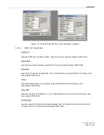
Page 37: ...s Note CalAmp DataCom recommends a Read be done anytime an initial connection is made to the TSLM Setup Port before accessing the Setup TSLM Parameters screen This will help the user avoid writing erroneous parameters to the connected unit Take note of the unit ID number being programmed This ID number will be used to create a diagnostic ID List 7 2 5 Port Settings TSLM programming is completed th...

Page 38: ...ary COM Ports Data Bits Selects the number of data bits 7 8 transmitted or received for the Primary and Secondary COM Ports Parity Selects transmission or reception of any Parity Bits for the Primary and Secondary COM Ports Stop Bits Selects number of Stop Bits 1 or 2 transmitted or received for the Primary and Secondary COM Ports DTR Enable Used to assert DTR Data Terminal Ready line of the RS232...

Page 39: ...ble 7 1 lists TSLM Communication Mode configurations Table 7 5 Communication Modes Mode Description Sync Esc with No HS Sends data using Sync byte stuffing protocol without handshaking Buffered with No HS Sends buffered data without handshaking This mode required for DOX operation Sync Esc with RTS CTS HS Sends data using the Sync Esc byte stuffing protocol with RTS CTS hardware handshaking Buffer...

Page 40: ...r to send line CTS is an input to the PC DSR DSR shows the current state of the DSR data set ready line DSR is an input to the PC DCD DCD shows the current state of the DCD data carrier detect line DCD is an input to the PC Bytes Tx ed Bytes Transmitted shows the number of bytes characters transmitted since the port was last opened or cleared Bytes Rx ed Bytes Received shows the number of bytes ch...

Page 41: ...ocal ID The Local ID is the Long ID of the unit connected to the computer The Short ID is displayed Remote ID The Remote ID combo box allows selection of the unit by choosing its Remote ID from which the Link Test information is gathered Remote IDs are set up in the Diagnostic IDs and Alarms Screen The Short ID is displayed An Offline Link Test returns the following statistics Blocks Tx ed to Remo...

Page 42: ...umber of blocks per transmission 1 to 200 blocks Block Delay s Block Delay s allows the user to determine the delay between data transmission blocks in 0 05 second intervals 0 00 to 120 00 seconds Clear Clear allows the user to clear the display blocks transmitted blocks received and link quality Start Start is used to begin the test Pause Pause is used to stop the test and allows the user to resu...

Page 43: ...voltage Analog Vcc Analog Circuits Regulated 5V line Temperature internal case temperature in Celsius RSSI Level Received Signal Strength Indication in dBm Forward Power Forward Power in watts Reverse Power Reverse Power in watts Preamble Good the number of correctly decoded transmissions received since power up Used with Preamble Total this serves as an indication of how well the unit is receivin...

Page 44: ... Truncated shows the user the Long and Short ID are not the same RSSI Level The RSSI level shows the current RSSI level in dBm while the Local unit is receiving Temperature Temperature shows the internal case temperature in Celsius Battery Voltage Battery Voltage shows the supply voltage in Volts Forward Power Forward Power shows forward power in Watts This parameter is available only when remote ...

Page 45: ...r pressing the Change Default Channel button Change Default Channel Change Default Channel allows the user to redirect the default Channel to another programmed channel Get Diags Stats The Get Diags button allows the user to send the command for Offline Diagnostics The command is sent to the unit connected to the computer if the Local ID button is selected The command is sent to the selected Remot...

Page 46: ...ta Only parameter programmed found on the Setup TSLM Parameters Screen Using Online Diagnostics does not require suspension of network operation Online Diagnostics are subject to alarm and filter conditions defined in the Diagnostic IDs Alarms and Filters parameters When Online Diagnostics are received and a diagnostic field falls outside the alarm limits a character will designate a value less th...

Page 47: ... remote modem is a TSLM Time Time is the time stamp when the diagnostics were received Short ID Filter List The Short ID Filter list allows the user to filter Short IDs Display Display allows the user to format on screen data The following options are available Scroll by time displays the diagnostics as they are received Slotted by ID sorts the diagnostics by Short ID Using this option each Short ...

Page 48: ...ntry allows the entry of a Long ID to be added to the ID List The range of this field is 1 to 4294967295 but multiples of 1024 should not be used A multiple of 1024 results in a Short ID of 0 If the Long ID is within the range of 1 to 1023 the Short ID will be the same or the resulting Short ID will be smaller than the Long ID and will be represented by a character in front of the ID A Long ID is ...

Page 49: ...erature diagnostics in degrees C Low High Batt Low High Batt represents the low and high limits for the battery voltage diagnostics in volts Low High Fwd Pwr Low High Fwd Pwr represents the low and high limits for the forward power diagnostics in watts Low High Rev Pwr Low High Rev Pwr represents the low and high limits for the Reverse Power diagnostics in watts Forward and Reverse Power diagnosti...

Page 50: ...t value of the parameters since the last Clear was performed or the last time power was removed Battery Voltage Battery Voltage shows the supply voltage in Volts Temperature Internal temperature in degrees Celsius RSSI Level Received Signal Strength Indication in dBm Preamble Good The number of correctly decoded transmissions received since power up Used with Preamble Total this serves as an indic...

Page 51: ... Power Level Tx Power Level allows the user to configure the Transmit Power Level for the User Test Clicking Default will return the Tx Power Level to the default value of 200 Tx Mode Tx Mode allows the user to select the transmit mode for the User Test The following modes are available No Modulation Random Data 100 Hz Tone 1200 Hz Tone Tx Time Tx Time allows the user to choose the transmit time f...

Page 52: ...ckets transmitted shows the number of data packets the Master has sent to the Remote Remote Packets Rx ed Host Packets received shows the number of data packets the Remote device has received from the Master Host to Remote Host to Remote percentage shows the percentage of packets the Host device has successfully sent to the Remote Remote Packets Tx ed Remote Packets transmitted shows the number of...

Page 53: ...e the same set this field to 1 Packet Delay s Packet Delay s is the number of seconds for the Host to delay between sending each packet This field ranges from 0 00 to 10 00 seconds in 0 25 second intervals Host Remote Host Remote is used to configure COM port options See Table 7 6 Host Primary Port Configures the primary COM port as the Host device the device initiating packets to the Remote devic...

Page 54: ...X X RI 9 X Requires connection No connection 7 2 13 Array Test The Array Test screen is used to send programmable length test packets Figure 7 15 Packet Test Screen Packets Tx ed Packets Tx ed shows the total number of packets transmitted of Packets to Send of Packets to Send allows the user to set the total number of packets to send before stopping field range is 0 to unlimited ...

Page 55: ...ngth and have a sequence number at the beginning of each string starting at 000 and incrementing to 999 then wrapping around to 000 again The pattern used to build the packets will have the following format in ASCII 000 00 11 22 33 44 55 66 77 88 99 AA BB CC DD EE FF 001 00 11 22 33 44 55 66 77 88 99 AA BB CC DD EE FF 998 00 11 22 33 44 55 66 77 88 99 AA BB CC DD EE FF 999 00 11 22 33 44 55 66 77 ...

Page 56: ...lay between each packet transmission ranging from 0 00 to 30 00 seconds in 0 25 second intervals Com Port Com Port allows the user to select the COM port primary or secondary for data transmission 7 2 14 Program Firmware The Program Firmware utility allows the user to update the TSLM firmware Contact Technical Services for more information 7 2 15 ASCII HEX TERMINAL Figure 7 16 ASCII Hex Terminal S...

Page 57: ... receives ASCII data on the Secondary COM Port set up in the Port Settings screen HEX Terminal Hex Terminal configurations include Primary The Primary Hex Terminal screen selects a Hexadecimal Terminal screen to send and receive Hexadecimal data on the Primary COM Port set up in the Port Settings screen Secondary The Secondary Hex Terminal screen selects a Hexadecimal Terminal screen to send and R...

Page 58: ...imum 4800 Baud Operating Mode Simplex or Half Duplex Front Panel Indicators PWR TX and RX Time out Timer Variable 0 120 seconds switchable on off Diagnostics Configuration test performance statistics Data Rate 4800 and 9600 bps Signal Levels EIA RS 232 Data Format Asynchronous serial transparent Word Length 7 or 8 bit words 1 or 2 stop bits Parity Even odd or none Transmit Control RTS CTS or Data ...

Page 59: ... 3 RECEIVER SPECIFICATIONS Bandwidth without tuning 406 422 MHz 16 MHz 137 162 MHz 25 MHz 414 430 MHz 16 MHz 150 174 MHz 24 MHz 450 470 MHz 20 MHz Reference Sensitivity 116dBm at 12dB SINAD and 1 kHz tone Adjacent Channel Rejection 60dB Spurious and Image Rejection 70dB per TIA EIA Intermodulation Rejection 70dB Rx Cold Start 100 mS from power on to Receive Data Audio Level 445 mVrms 180 145 mVrms...

Page 60: ...RY AND INDUSTRY SPECIFICATIONS TIA EIA All specifications per TIA EIA 603 unless otherwise noted FCC UHF NP4 2422240510 9K60F1D and 10K0F1D VHF NP4 2422210610 9K60F1D and 10K0F1D IC UHF 773B 2240510 9K60F1D and 10K0F1D VHF 773B 2210610 9K60F1D and 10K0F1D ...

Page 61: ...so request an RMA online at www dataradio com rma When returning a product mark the RMA clearly on the outside of the package Include a complete description of the problem and the name and telephone number of a contact person RETURN REQUESTS WILL NOT BE PROCESSED WITHOUT THIS INFORMATION For units in warranty customers are responsible for shipping charges to CalAmp DataCom For units returned out o...

Page 62: ...bligations on the part of DRL This warranty is void and DRL shall not be obligated to replace or repair any Products if i the Product has been used in other than its normal and customary manner ii the Product has been subject to misuse accident neglect or damage or has been used other than with DRL approved accessories and equipment iii unauthorized alteration or repairs have been made or unapprov...

Reviews: