background image

2-56 x ½” SH

Plastic Ride Height
Spacers 3, 4, 5mm

Delrin

Pivot Ball

CRC Pro-Strut

Front End

2-56 Red

Locknut

4-40 x 7/16”

Red FH

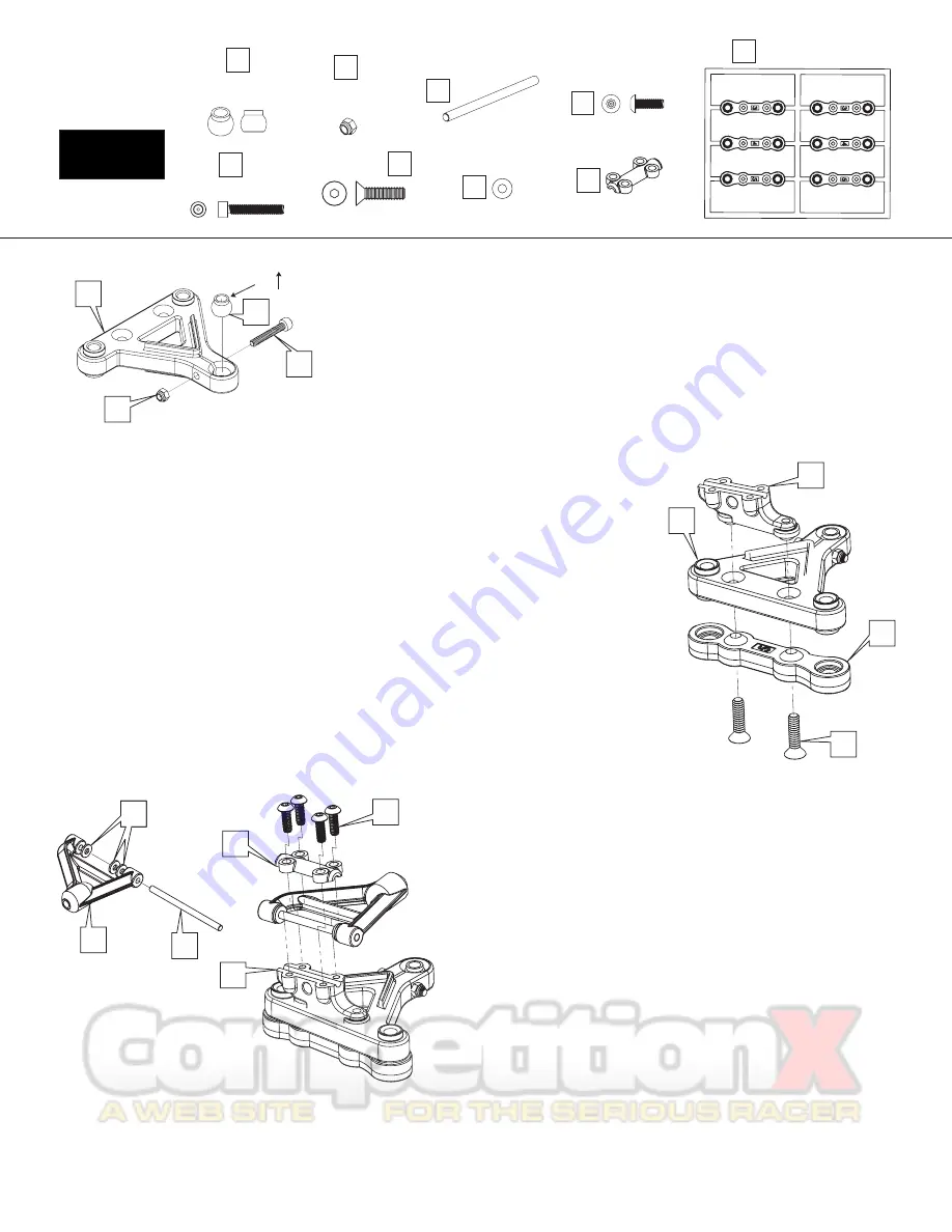
1 - Pop the delrin pivot ball [49] into the lower arm [50]. Place the arm on a strong table and push
the ball in with the back of screwdriver handle. Or preferably, you can use CRC’s 4279 Ball popper
pivot ball tool. Notice the “lip” of the delrin pivot ball is pointing upward. The diagram to the left
represents a right side lower arm. For the left side, flip the second arm over and be sure the pivot
ball is installed with the lip again facing up.

2 - Once the ball is popped in, insert the black 2-56 clamp screw [51] through the horizontal hole in
the lower arm. Thread the 2-56 red locknut [52] onto the black screw. Tighten the screw slowly
continuously checking the pivot ball. When it begins to bind a bit, back the 2-56 screw off a bit. The
ball should be free to pivot with just a bit of drag. There is no need to have this ball super loose and
free, a slight drag will be just the right amount of clamping force.

Check this fit after a few runs as the ball will wear and require additional clamping force.

Lip

1 - Install the upper A-arm mount [53] with the amount of Dynamic Caster desired. The options are 0, 5 and 10
degrees. The part shown to the right in the diagram is the 5 degree version and is a good starting point. The
10 will angle down more toward the front of the car with the 0 being parallel to the chassis. The general
thought is the more Dynamic Caster, more steering the car will have at corner entry.

2 - With side cutters or good scissors, cut off (do NOT break off) the 3, 4 and 5 mm spacers [54] from the ride
height tree. Use the 5 mm thickness for 1/10th scale tires. For fine front ride height adjustments, use the CRC
#4262 optional front shim set. This set contains .010, .020 and .030” plastic ride height shims. After selecting
the proper spacer, push the red 4-40 x 7/16” screw [55] through the plastic ride height spacer [54], then
through the lower arm [50], and then thread the screw into the upper A-arm mount [53]. Be sure NOT to over
tighten. Just snug, you are threading an aluminum screw into the plastic upper A-arm mount.

49

49

50

51

51

52

52

53

54

55

54

50

55

Bag F

10

1 - Break the mold tree from the upper A-arm [56]. You can clean up the
mold gates with a hobby knife or rotary tool.

2 - Locate the upper arm hinge pin [57] and slide it into one half of the upper
arm. Locate 3 small caster shims [58]. Push the hinge pin through the 3
shims. Then continue to push the hinge pin all the way into the upper arm.

3 - Now, install the arm/pin/washer assembly onto the upper arm mount [53].
Put the hinge pin in the channel. At this point you can set your starting
caster setting by moving these washers forward and back. The position
shown to the left will result in a competitive handling. Moving them to the
rear will increase steering from the center and exit of the corner.

If the fit of the upper arm is tight, trim the upper arm mount SLIGHTLY with a
hobby knife.

4 - Install the upper cap [59] with 4 black 2-56 button head screws [60]. The
topper is the “clamp” for the hinge pin. Be sure to tighten so that any gap is
gone, however, do not tighten beyond that point as damage can occur to the
upper a-arm mount holes.

56

57

58

53

59

Hinge Pin

57

Caster Shim

58

2-56 BH

60

Upper Cap

59

60

Summary of Contents for Carpet Knife Generation X 10

Page 1: ...Carpet Knife Generation X Gen X 10 Assembly Manual Calandra Racing Concepts Inc 6785 Martin St Rome NY 13440 Phone Fax 315 338 0867 www teamcrc com information teamcrc com...

Page 2: ...ghten the 2 56 flat heads 2 enough to remove any up and down play be sure the flanged pivot ball 4 pivots freely Red Locknut 1 Place the 4 40 x 3 8 screws 5 through the graphite chassis 6 in the holes...

Page 3: ...e that the rear bottom plate and chassis are in a straight line flat against the table again no tires on the car Lightly tap the chassis and rear pod releasing any tension in the links Keep the chassi...

Page 4: ...e bottom of the graphite top plate 17 so that the threads point upward Slide two washers 8 over the screw and then tighten with the red female ballstud 18 3 Install the Graphite X brace 19 to the back...

Page 5: ...Add a dab of super glue to keep these 2 parts secure to each other Metal Spring Holder Graphite Tweak Plate x2 INSERT TWEAK SCREWS IN BRACE ASSEMBLY 1 Place the Tweak Brace 24 on a smooth flat table a...

Page 6: ...spring 27 into the groove on the metal retainer 26 Pull the leading coil over the retainer and place the top coil into the groove Then holding the retainer securely turn the spring clockwise to open t...

Page 7: ...llen key Leave about 1 8 protruding 4 Thread the 2 ball cups into their respective tube halves per the diagram Finger tighten 5 Add CRC Tube Lube 34 to each slot on the delrin plunger 35 Build the tub...

Page 8: ...e completed mounting brackets and line it up with the holes in the chassis as shown in the diagram to the left The captive nut should line up with the dimple cut out of the chassis 2 Slide one of the...

Page 9: ...his in bag 7 8 4 40 x 1 8 Set Screw 45 41 44 43 42 9 23 46 45 47 1 Attach the completed center shock mount to the Top Deck 46 using two 4 40 x 1 4 red FH screws 23 in the holes shown in the diagram 2...

Page 10: ...t that we had temporarily bolted on earlier 2 Slide the screw through one of the graphite plates and place one of the washers over the screw Now insert the screw through the shock ball Insert the seco...

Page 11: ...utters or good scissors cut off do NOT break off the 3 4 and 5 mm spacers 54 from the ride height tree Use the 5 mm thickness for 1 10th scale tires For fine front ride height adjustments use the CRC...

Page 12: ...nd slide it through the lower arm pivot ball 49 then thread it into the steering block with the steering block all the way down against the pivot ball Thread the king pin in until the spring just touc...

Page 13: ...secure the front end assembly to the plate using the 8 32 x low head front end screws 74 Again we recommend starting in the middle hole giving you the option to go longer or shorter 3 Repeat these ste...

Page 14: ...he servo saver from the front and then secure them with a red locknut 9 on the back Mount the servo saver to the servo 2 Slide a washer 8 over each of the 4 40 x 3 8 red cap head screws 78 Now slide t...

Page 15: ...diff ring 90 and then a 1 4 x 3 8 plain bearing 91 over the end of the axle Align the diff ring so that it notches into the axle flange Place the assembled gear with the greased diff balls over the ax...

Page 16: ...ith the set screw 15 45 78 Adjust body height by raising or lowering this collar 99 98 45 97 96 M3 x 8mm Steel Button Head 97 Two rear body mount locations Bag 11 4 40 x 3 8 Red Socket Cap 3 16 Shim 3...

Page 17: ...crew Set CK 23 4 40 x 1 4 alum flathead 1410 Andzd Alum Screw Set CK 24 Graphite Tweak Plate 1770 Graphite Side Plate GenX 10 25 Tweak Screw 1288 5 16 x 4 40 set screw twk 3 2 Gen X 26 Metal Spring Ho...

Page 18: ...Red Spring 1297 Side Spring Red firm 1280 Rear Side Spring Set 67 E Clip 1382 1 8 E clips 100 pieces 68 Brass Set Screw 3234 Brass 4 40 Set screws 2 pr 69 Nylon Spring Cup 3287 Nylon Spring Cup 70 Upp...

Page 19: ...ut 4126 8 32 Nylon Locknut 2 96 Front Body Post 1778 Body Post Set Short GX10 BA 97 M3 x 8mm Steel Button Head 1490 3mm x 8mm Steel Button Head 98 Rear Body Post 1779 Body Post Set Long GX10 BA 99 Bod...

Reviews: