Snowball board System
Architecture and Design
47
the A9500 processor. The 38.4Mhz clock is sent into the internal circuitry of the AB8500 (input of
the 27Mhz PLL which is used internally for the DENC part of TVout and provided on the CLK27M
ball and the USB OTG phy interface). The APECLK of the A9500 Nova processor is supplied by the
ULPCLK output of the AB8500. Indeed, inside the AB8500 an internal PLL (ULP) supplied by the
32Khz generates a 38.4Mhz clock for the APE part of the A9500.
8.9. USB OTG Port
The main USB port on the Snowball board is a USB OTG port. It can be used as an OTG port or client
port. In order to use the OTG in the HOST mode, the Snowball board must be powered by an +5V
external supply or by a Li-ion battery.
8.9.1. USB OTG Overview
USB OTG is a supplement to the USB 2.0 specification. The standard USB uses a master/slave
architecture, a USB host acting as a master and a USB peripheral acting as a slave. Only the USB host
can schedule the configuration and data transfers over the link. The USB peripherals cannot initiate
data transfers, they only respond to instructions given by a host.
USB OTG works differently in that gadgets don't need to be pure peripherals because they can
sometimes act as hosts. An example might be connecting a USB keyboard or printer to a Snowball
board or a USB printer that knows how to grab documents from certain peripherals and print them.
The USB OTG compatible devices are able to initiate the session, control the connection and exchange
Host/Peripheral roles between each other.
The USB OTG supplement does not prevent the use of a hub, but it describes role swapping only in
the case of a one-to-one connection where two OTG devices are directly connected. If a standard hub
is used, the supplement notes that using it will lead to losing USB OTG role-swap capabilities making
one device act as the Default-Host and the other as the Default-Peripheral until the hub is disconnected.
The combination of the A9500 and the AB8500 allows the Snowball board to work as an OTG device
if desired. The primary mode of operation however, is intended to be a client mode in order to pull
power from the USB host which is typically a PC. As the Snowball board does not have a Host USB
port, this port will be used as a Host port in many applications.
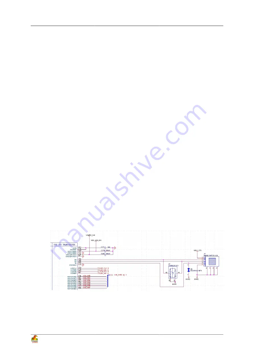
8.9.2. USB OTG Design
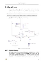
Figure 8.15 illustrates the design of the USB OTG port on the Snowball board.
Figure 8.15. USB OTG Design
8.9.3. OTG ULPI Interface
ULPI is an interface standard for high-speed USB 2.0 systems. It defines an interface between USB
link controller (processor) and the AB8500 that drives the actual bus. ULPI stands for UTMI+ low pin
Summary of Contents for SKY-S9500-ULP-CXX
Page 1: ...SKY S9500 ULP CXX aka Snowball PDK SDK Hardware Reference Manual Revision 1 0 July 1 2011...
Page 3: ...SKY S9500 ULP CXX aka Snowball PDK SDK 3...
Page 17: ...Snowball board Overview 8 Figure 4 2 Snowball board Usage Scenarios...
Page 89: ...Connnector Pinouts and Cables 80 Figure 9 17 Location of R77...
Page 92: ...Mechanical Information 83 Figure 11 2 Board Mechanical drawing...
Page 93: ...Troubleshooting 84 Chapter 12 Troubleshooting 12 1 TBD TBD...
Page 94: ...Known Issues 85 Chapter 13 Known Issues TBD...
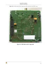
Page 96: ...PCB Component Locations 87 Figure 14 2 Snowball board Bottom Side Components...
Page 97: ...Schematics 88 Chapter 15 Schematics Figure 15 1 AB8500 1 2...
Page 98: ...Schematics 89 Figure 15 2 AB8500 2 2...
Page 99: ...Schematics 90 Figure 15 3 Power circuitry and serial port...
Page 100: ...Schematics 91 Figure 15 4 AP9500 1 4...
Page 101: ...Schematics 92 Figure 15 5 AP9500 2 4...
Page 102: ...Schematics 93 Figure 15 6 AP9500 3 4...
Page 103: ...Schematics 94 Figure 15 7 AP9500 4 4...
Page 104: ...Schematics 95 Figure 15 8 Reset circuitry and Audio in out...
Page 105: ...Schematics 96 Figure 15 9 HMDI circuitry...
Page 106: ...Schematics 97 Figure 15 10 Sensors...
Page 107: ...Schematics 98 Figure 15 11 WLAN Bluetooth GPS...
Page 108: ...Schematics 99 Figure 15 12 eMMC and microSD...
Page 109: ...Schematics 100 Figure 15 13 Expansion connector...
Page 110: ...Schematics 101 Figure 15 14 Ethernet 10 100M...

