SKY-S9500-ULP-CXX
(aka Snowball PDK-SDK)
vii
List of Figures
4.1. Snowball board Usage Scenarios ............................................................................... 7
4.2. Snowball board Usage Scenarios ............................................................................... 8
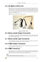
5.1. USB Y-cable ........................................................................................................ 11
6.1. The Box .............................................................................................................. 15
6.2. Box Contents ....................................................................................................... 16
7.1. USB OTG Connection ........................................................................................... 17
7.2. DC Power Connection ........................................................................................... 18
7.3. Li-ion battery Connection ....................................................................................... 19
7.4. JTAG Connection ................................................................................................. 20
7.5. MIPI Debug Connection ......................................................................................... 21
7.6. Mini-b USB connector ........................................................................................... 22
7.7. Serial Cable Connection ......................................................................................... 23
7.8. CVBS Connection ................................................................................................. 24
7.9. HDMI Connection ................................................................................................. 25
7.10. Audio Out Cable Connection ................................................................................. 26
7.11. Audio In Cable Connection ................................................................................... 27
7.12. Indicator Locations .............................................................................................. 28
7.13. Button Location .................................................................................................. 29
7.14. microSD Card Location ........................................................................................ 30
7.15. uFL connectors Location ...................................................................................... 31
8.1. Block diagram ...................................................................................................... 32
8.2. PDK Top side Components ..................................................................................... 33
8.3. PDK Bottom side Components ............................................................................... 34
8.4. SDK Top side Components ..................................................................................... 35
8.5. Input Power Section .............................................................................................. 36
8.6. VBAT Power Conditioning ..................................................................................... 38
8.7. VBAT Power Conditioning ..................................................................................... 39
8.8. Peripheral Voltages ............................................................................................... 40
8.9. Power Sequencing ................................................................................................. 42
8.10. Reset Circuitry .................................................................................................... 43
8.11. A9500 Block Diagram .......................................................................................... 44
8.12. MSP Block diagram ............................................................................................. 45
8.13. PoP Memory ...................................................................................................... 46
8.14. System clocks ..................................................................................................... 46
8.15. USB OTG Design ............................................................................................... 47
8.16. Ethernet 10/100 ................................................................................................... 50
8.17. AW-NH580 Block Diagram .................................................................................. 51
8.18. Micro SD Card ................................................................................................... 53
8.19. HDMI interface design ......................................................................................... 55
8.20. CVBS interface ................................................................................................... 59
8.21. RS232 port ......................................................................................................... 59
8.22. RS232 Cable ...................................................................................................... 60
8.23. JTAG Interface ................................................................................................... 61
9.1. Power Connector ................................................................................................... 68
9.2. USB OTG Connector ............................................................................................. 68
9.3. CVBS-Video Connector ......................................................................................... 69
9.4. HDMI Connector .................................................................................................. 69
9.5. Audio in Plug ....................................................................................................... 70
9.6. Audio in Receptacle .............................................................................................. 70
9.7. Audio Out Plug .................................................................................................... 71
9.8. Audio Out Receptacle ............................................................................................ 71
9.9. JTAG Connector Pinout ......................................................................................... 72
9.10. MiPi Debug Connector ......................................................................................... 73
9.11. RS232 Header ..................................................................................................... 74
9.12. RS232 Cable ...................................................................................................... 75
Summary of Contents for SKY-S9500-ULP-CXX
Page 1: ...SKY S9500 ULP CXX aka Snowball PDK SDK Hardware Reference Manual Revision 1 0 July 1 2011...
Page 3: ...SKY S9500 ULP CXX aka Snowball PDK SDK 3...
Page 17: ...Snowball board Overview 8 Figure 4 2 Snowball board Usage Scenarios...
Page 89: ...Connnector Pinouts and Cables 80 Figure 9 17 Location of R77...
Page 92: ...Mechanical Information 83 Figure 11 2 Board Mechanical drawing...
Page 93: ...Troubleshooting 84 Chapter 12 Troubleshooting 12 1 TBD TBD...
Page 94: ...Known Issues 85 Chapter 13 Known Issues TBD...
Page 96: ...PCB Component Locations 87 Figure 14 2 Snowball board Bottom Side Components...
Page 97: ...Schematics 88 Chapter 15 Schematics Figure 15 1 AB8500 1 2...
Page 98: ...Schematics 89 Figure 15 2 AB8500 2 2...
Page 99: ...Schematics 90 Figure 15 3 Power circuitry and serial port...
Page 100: ...Schematics 91 Figure 15 4 AP9500 1 4...
Page 101: ...Schematics 92 Figure 15 5 AP9500 2 4...
Page 102: ...Schematics 93 Figure 15 6 AP9500 3 4...
Page 103: ...Schematics 94 Figure 15 7 AP9500 4 4...
Page 104: ...Schematics 95 Figure 15 8 Reset circuitry and Audio in out...
Page 105: ...Schematics 96 Figure 15 9 HMDI circuitry...
Page 106: ...Schematics 97 Figure 15 10 Sensors...
Page 107: ...Schematics 98 Figure 15 11 WLAN Bluetooth GPS...
Page 108: ...Schematics 99 Figure 15 12 eMMC and microSD...
Page 109: ...Schematics 100 Figure 15 13 Expansion connector...
Page 110: ...Schematics 101 Figure 15 14 Ethernet 10 100M...


