Connnector Pinouts and Cables
72
9.7. JTAG
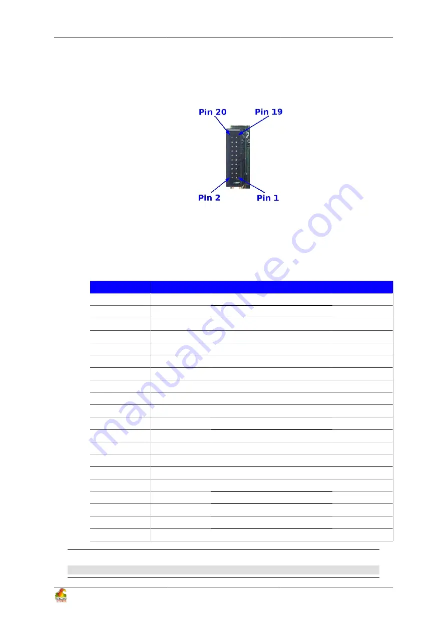
Figure 9.9 is the JTAG connector pin out showing the pin numbering.
Figure 9.9. JTAG Connector Pinout
Table 9.2 gives a definition of each of the signals on the JTAG Header.
Table 9.2. JTAG Signals
Pin
Signal Name
Description
I/O
1
VSMPS2_1V8
Level voltage reference
PWR
2
NC
3
TRST_n
Test Reset
IN
4
GND
Ground
PWR
5
TDI
Test data input
IN
6
GND
Ground
PWR
7
TMS
Test mode select
IN
8
GND
Ground
PWR
9
TCK
Test Clock
IN
10
GND
Ground
PWR
11
NC
12
GND
Ground
PWR
13
TDO
Test Data Output
OUT
14
GND
Ground
PWR
15
SRST_N
System Reset
IN
16
GND
Ground
PWR
17
NC
18
GND
Ground
PWR
19
NC
20
GND
Ground
PWR
Warning
All of the signals are 1.8V !
Summary of Contents for SKY-S9500-ULP-CXX
Page 1: ...SKY S9500 ULP CXX aka Snowball PDK SDK Hardware Reference Manual Revision 1 0 July 1 2011...
Page 3: ...SKY S9500 ULP CXX aka Snowball PDK SDK 3...
Page 17: ...Snowball board Overview 8 Figure 4 2 Snowball board Usage Scenarios...
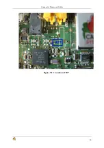
Page 89: ...Connnector Pinouts and Cables 80 Figure 9 17 Location of R77...
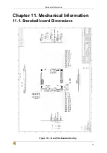
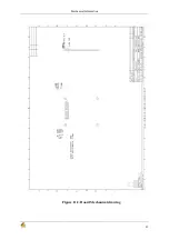
Page 92: ...Mechanical Information 83 Figure 11 2 Board Mechanical drawing...
Page 93: ...Troubleshooting 84 Chapter 12 Troubleshooting 12 1 TBD TBD...
Page 94: ...Known Issues 85 Chapter 13 Known Issues TBD...
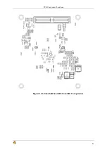
Page 96: ...PCB Component Locations 87 Figure 14 2 Snowball board Bottom Side Components...
Page 97: ...Schematics 88 Chapter 15 Schematics Figure 15 1 AB8500 1 2...
Page 98: ...Schematics 89 Figure 15 2 AB8500 2 2...
Page 99: ...Schematics 90 Figure 15 3 Power circuitry and serial port...
Page 100: ...Schematics 91 Figure 15 4 AP9500 1 4...
Page 101: ...Schematics 92 Figure 15 5 AP9500 2 4...
Page 102: ...Schematics 93 Figure 15 6 AP9500 3 4...
Page 103: ...Schematics 94 Figure 15 7 AP9500 4 4...
Page 104: ...Schematics 95 Figure 15 8 Reset circuitry and Audio in out...
Page 105: ...Schematics 96 Figure 15 9 HMDI circuitry...
Page 106: ...Schematics 97 Figure 15 10 Sensors...
Page 107: ...Schematics 98 Figure 15 11 WLAN Bluetooth GPS...
Page 108: ...Schematics 99 Figure 15 12 eMMC and microSD...
Page 109: ...Schematics 100 Figure 15 13 Expansion connector...
Page 110: ...Schematics 101 Figure 15 14 Ethernet 10 100M...


