SnowBall board Specification
11
5.5. HS USB 2.0 OTG Port
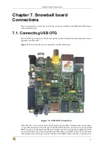
The USB OTG port can be used as the primary power source and communication link for the Snowball
board and derives power from the PC over the USB cable. The client port is limited in most cases
to 500mA by the PC. A single PC USB port is sufficient to power the Snowball board. If additional
devices are connected to the expansion connectors and the Vbat rail is used, then the power required
could exceed that supplied by a USB port or Hub. It is possible to take the current supplied by the
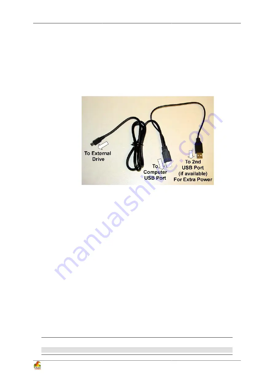
USB ports to 1A by using a Y cable.
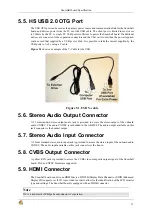
Figure 5.1 shows an example of the Y-Cable for the USB.
Figure 5.1. USB Y-cable
5.6. Stereo Audio Output Connector
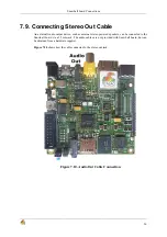
A 3.5mm standard stereo output audio jack is provided to access the stereo output of the onboard
audio CODEC. The audio CODEC is embedded in the AB8500. The audio output available on this
jack connector is the headset output.
5.7. Stereo Audio Input Connector
A 3.5mm standard stereo audio input jack is provided to access the stereo input of the onboard audio
CODEC. The audio input available on this jack connector is the line-in.
5.8. CVBS Output Connector
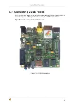
A yellow RCA jack is provided to access the CVBS video composite output signal of the Snowball
board. PAL and NTSC format are supported.
5.9. HDMI Connector
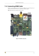
The Snowball board can drive an HDMI device. DDC2B (Display Data Channel) or EDID (Enhanced
Display ID) support over I2C® is provided in order to allow for the identification of the LCD monitor
type and settings. The Snowball board is equipped with an HDMI connector.
Note
I2C is a trademark of Philips Semiconductors Corporation
Summary of Contents for SKY-S9500-ULP-CXX
Page 1: ...SKY S9500 ULP CXX aka Snowball PDK SDK Hardware Reference Manual Revision 1 0 July 1 2011...
Page 3: ...SKY S9500 ULP CXX aka Snowball PDK SDK 3...
Page 17: ...Snowball board Overview 8 Figure 4 2 Snowball board Usage Scenarios...
Page 89: ...Connnector Pinouts and Cables 80 Figure 9 17 Location of R77...
Page 92: ...Mechanical Information 83 Figure 11 2 Board Mechanical drawing...
Page 93: ...Troubleshooting 84 Chapter 12 Troubleshooting 12 1 TBD TBD...
Page 94: ...Known Issues 85 Chapter 13 Known Issues TBD...
Page 96: ...PCB Component Locations 87 Figure 14 2 Snowball board Bottom Side Components...
Page 97: ...Schematics 88 Chapter 15 Schematics Figure 15 1 AB8500 1 2...
Page 98: ...Schematics 89 Figure 15 2 AB8500 2 2...
Page 99: ...Schematics 90 Figure 15 3 Power circuitry and serial port...
Page 100: ...Schematics 91 Figure 15 4 AP9500 1 4...
Page 101: ...Schematics 92 Figure 15 5 AP9500 2 4...
Page 102: ...Schematics 93 Figure 15 6 AP9500 3 4...
Page 103: ...Schematics 94 Figure 15 7 AP9500 4 4...
Page 104: ...Schematics 95 Figure 15 8 Reset circuitry and Audio in out...
Page 105: ...Schematics 96 Figure 15 9 HMDI circuitry...
Page 106: ...Schematics 97 Figure 15 10 Sensors...
Page 107: ...Schematics 98 Figure 15 11 WLAN Bluetooth GPS...
Page 108: ...Schematics 99 Figure 15 12 eMMC and microSD...
Page 109: ...Schematics 100 Figure 15 13 Expansion connector...
Page 110: ...Schematics 101 Figure 15 14 Ethernet 10 100M...


