Snowball board Connections
17
Chapter 7. Snowball board
Connections
This section provides an overview of all of the connectors available on the PDK and SDK versions
of the Snowball board.
7.1. Connecting USB OTG
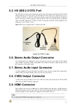
The USB OTG port connects to the PC host and uses a Mini-AB cable through which power can be
provided to the Snowball.
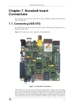
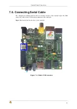
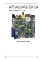
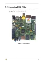
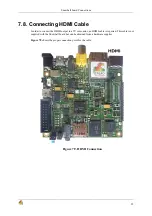
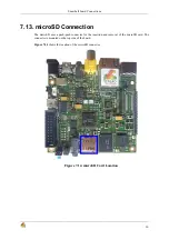
Figure 7.1 shows where the cable is connected to the Snowball board.
Figure 7.1. USB OTG Connection
If the OTG Port is to be used as a Host, the ID pin must be grounded. This means that you must have
a 5 pin cable connected to the OTG port on the Snowball board and you must use a powered USB
HUB. You can power the board from this port, but there may not be enough power supplied by the PC
to power all features. If you use the double ended USB cable, you should be able to power the board
with minimal issues as long as you do not load down the USB Host ports with heavy current devices.
Summary of Contents for SKY-S9500-ULP-CXX
Page 1: ...SKY S9500 ULP CXX aka Snowball PDK SDK Hardware Reference Manual Revision 1 0 July 1 2011...
Page 3: ...SKY S9500 ULP CXX aka Snowball PDK SDK 3...
Page 17: ...Snowball board Overview 8 Figure 4 2 Snowball board Usage Scenarios...
Page 89: ...Connnector Pinouts and Cables 80 Figure 9 17 Location of R77...
Page 92: ...Mechanical Information 83 Figure 11 2 Board Mechanical drawing...
Page 93: ...Troubleshooting 84 Chapter 12 Troubleshooting 12 1 TBD TBD...
Page 94: ...Known Issues 85 Chapter 13 Known Issues TBD...
Page 96: ...PCB Component Locations 87 Figure 14 2 Snowball board Bottom Side Components...
Page 97: ...Schematics 88 Chapter 15 Schematics Figure 15 1 AB8500 1 2...
Page 98: ...Schematics 89 Figure 15 2 AB8500 2 2...
Page 99: ...Schematics 90 Figure 15 3 Power circuitry and serial port...
Page 100: ...Schematics 91 Figure 15 4 AP9500 1 4...
Page 101: ...Schematics 92 Figure 15 5 AP9500 2 4...
Page 102: ...Schematics 93 Figure 15 6 AP9500 3 4...
Page 103: ...Schematics 94 Figure 15 7 AP9500 4 4...
Page 104: ...Schematics 95 Figure 15 8 Reset circuitry and Audio in out...
Page 105: ...Schematics 96 Figure 15 9 HMDI circuitry...
Page 106: ...Schematics 97 Figure 15 10 Sensors...
Page 107: ...Schematics 98 Figure 15 11 WLAN Bluetooth GPS...
Page 108: ...Schematics 99 Figure 15 12 eMMC and microSD...
Page 109: ...Schematics 100 Figure 15 13 Expansion connector...
Page 110: ...Schematics 101 Figure 15 14 Ethernet 10 100M...


