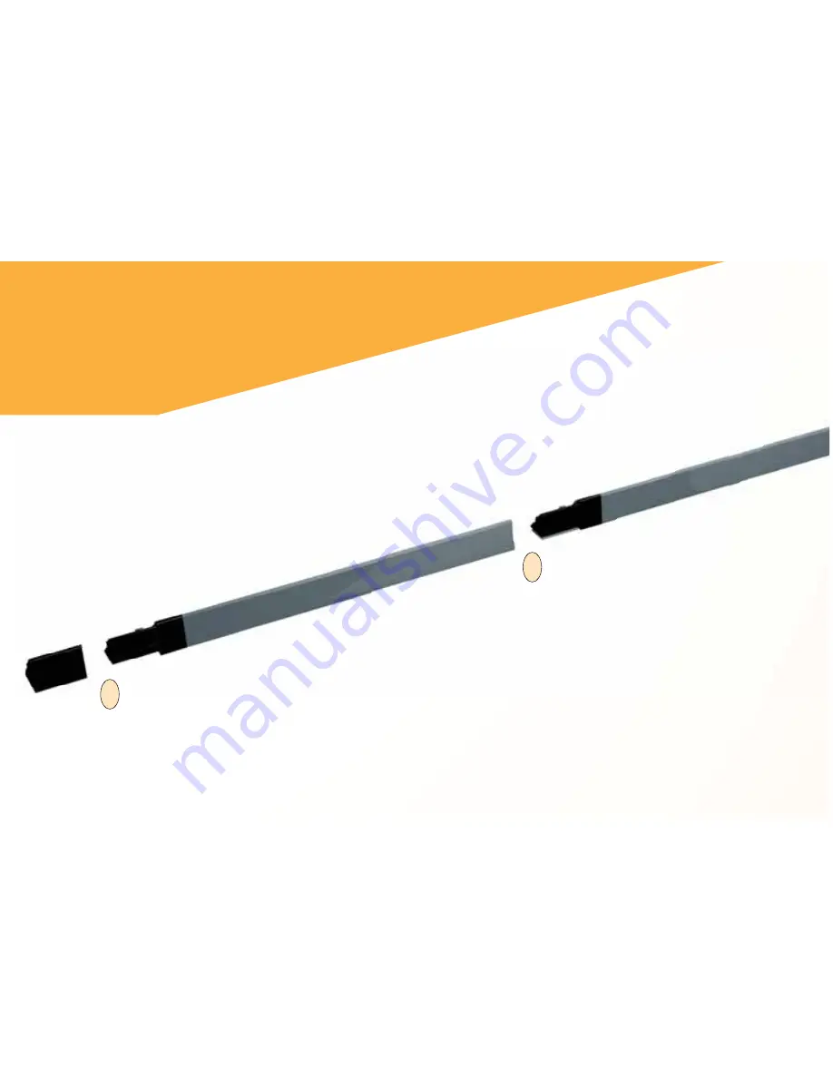
NOTE: Sloping side of the Refl ector
Bars face outward.
5. Insert the the male end of
the second Long Refl ector
Bar into the female end of
the Short Refl ector Bar.
3
4. Insert the male end of the Short Refl ector
Bar into the Female Bar End Cap.
4
LEFT-HAND ASSEMBLY
Assemble the refl ector bars as shown. Align
the corner connector at a 90° angle at the
top right corner of the plans.
6 — U
LTRA
S
CALE
M
ASTER
®
P
RO
Summary of Contents for 6260
Page 1: ...USER S GUIDE Area Take Off Tool and Digitizing System Model 6260...
Page 11: ...Right Hand Configuration Shown USER S GUIDE 9...
Page 51: ......
Page 52: ......


