Caledonian Audio
6BM8-ECL82-SE-Classique Assembly Manual
41
41
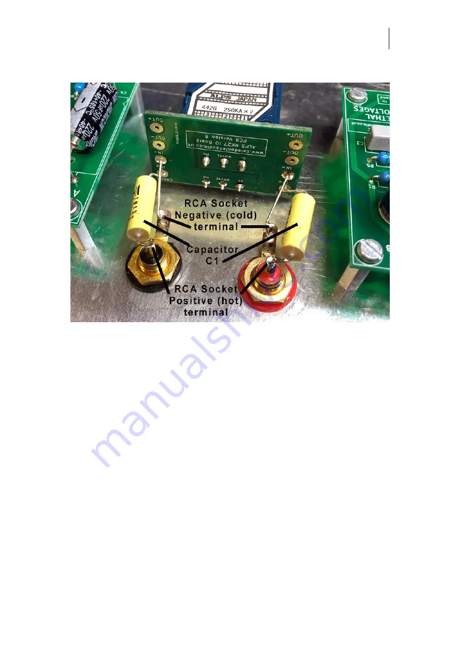
RCA Terminals to Potentiometer PCB
Referring to
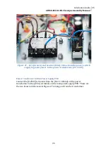
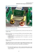
Figure 34 Connecting the RCA input connectors to the potentiometer IO PCB
Potentiometer PCB to Amplifier PCB
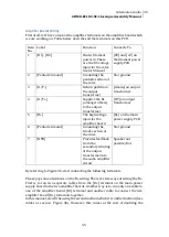
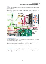
We will now connect the audio signal from the potentiometer PCB to both of the
amplifier PCBs.
Bearing in mind that we are working on CHAN1 side of the potentiometer (please
refer to Figure 35):
1.
Connect the [OUT+] on potentiometer PCB to the [Audio In +] on the
amplifier board
2.
Connect the [OUT-] on potentiometer PCB to the [Audio In –] (on the
amplifier board)
Do the same for CHAN2 side of the potentiometer board (but connect to the other
amplifier board).
Some might choose to use screened cables for connecting the potentiometer to the
amplifier board. Whilst screened cables are highly recommended, please make
sure that only one end of the screen is connected to 0V (ground) level.
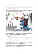
1.
Place and solder Capacitor C1 so that it connects the RCA positive (hot)
terminal and the [IN+] terminal on the potentiometer PCB. Do this for both
Chan1 and Chan2
Summary of Contents for 6BM8/ECL82 SE
Page 1: ...Assembly Manual 6BM8 ECL82 SE 2 5W Classique MKII Version 3 0 Caledonian Audio ...
Page 6: ...6 ...
Page 10: ...10 Figure 2 Filament supply board with the four diodes ...
Page 16: ...16 Figure 8 Main power supply PCB fully populated ...


