22
SPECIFIC PROCEDURES
First battery insertion within actuator/actuator still unbound to controller
After fitting the batteries for the first time, the actuator LED will blink twice. LED will continue blinking twice every 2 minutes to indicate the binding to controller has not been performed
yet.
Checking the communication level between the actuator and controller
The controller should be ON and working, the actuator should be correctly bound to the controller. Touch simultaneously two opposite buttons on the actuator (for example the lower left
one and the upper right one). Immediately after the release, a check can be performed through the LED:
- LED blinking 4 times: communication level OPTIMUM
- LED blinking 3 times: communication level REASONABLE
- LED blinking 2 times: communication level SUFFICIENT
- LED ON for 2 seconds means the actuator did not receive any signal from the controller. Evaluate the necessity of installing a signal repeater.
Manual opening/closing of actuator
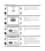
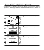
Select on the controller: MENU-INSTALLATION-ZONE MANAGEMENT-ZONE MODIFICATION-[select the zone corresponding to the actuator]-TEST-OPEN/CLOSE.
On the display request, touch simultaneously two opposite buttons on the actuator for 2 seconds. Immediately after the release, a check can be performed through the LED:
- LED ON for 1 second, command signal wan not received. The actuator does not perform any action.
- LED blinking every 0,5 seconds, command signal was received; LED continues blinking for all the activation period of the actuator. The actuator performs a full opening or closing
procedure. We suggest to perform the operation with the actuator already installed on the valve.
RESETTING the actuator to factory settings
It’s possible to reset the actuator to factory settings. In this case, the binding to the controller will be lost. We suggest the perform this operation only in case of extreme necessity. After
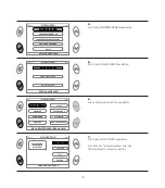
performing this operation, the binding actuator-controller should be deleted through the specific function MENU INSTALLATION on the controller.
Touch simultaneously the two lower buttons on the actuator (below Caleffi logo) for 2 seconds. The actuator LED blinks for 4 seconds, during which it is necessary to touch
simultaneously the two upper buttons on the actuator. The motor will move to the fully open position and the binding identification number on the controller is deleted. The actuator LED
gets ON for 2 seconds. The actuator gets into the status “batteries fitted, actuator unbound to any controller”.
FAULTS
In case of working faults, the icon
. appears on the main menu screen. Selecting the icon and pressing OK, it is possible to visualize current faults in the next screens. A fault is
put into evidence also by the “stand by” screen: usually this screen displays time and Caleffi logo in white; in case of problems, characters get red.
Low batteries - replacement
If the actuator battery charge is too low for
normal operation, the problem is indicated by the symbol
on the controller display. The
actuator LED blinks three times every ten minutes. The actuator automatically moves to the
opening position=50%. The battery replacement does not cause the loss of binding to the
controller. To replace batteries:
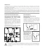
1) Extract the actuator cover by pushing the squared locking pin with the point of a pen.
Pull the cover according to the arrow dirction.
2) Fit two AA 1,5 V batteries respecting the polarity. The actuator LED will blink twice for one
second. Close the cover again.
Loss of communication between actuator (or other radio wave device) and controller
In case of loss of communication between the actuator and controller for more than 40 minutes, the problem is indicated by the symbol
on the display. Selecting the icon,
the display will show the information about the actuator which lost the communication.
Each actuator is assigned with a number from 1 to 4 according to the binding order to the controller. In order to guarantee anyway the ambient temperature adjustment, the
actuator adjusts with a fixed set point of 20°C by using its inner temperature sensor.
Verify if the device are intact, the radio wave signal range is sufficient (see test function), the actuator batteries are fully charged, the temperature sensor is correctly lighted (to
have enough charge for signal transmission).
The controller display is OFF
Verify if the controller is electrically supplied and the supply is correctly connected (correct polarity). In case of negative response, please contact Caleffi technical support.
The room temperature is different w.r.t the set value
To perform the observation, it’s necessary to wait for a reasonable time since the set point definition.
Verify the proper boiler working and the radiator valve correct functioning (verify the battery charge level, perform an opening/closing test to check they are not clogged). Actuator should
correctly measure the room temperature. Verify that the measured temperature value is aligned with the room one with the function “INFO”. Check if the ambient temperature sensor (if
installed) is correctly placed and not exposed to direct light (which could impair the temperature reading). .if not present, please evaluate the use of a ambient temperature sensor In
case of negative response, please contact Caleffi technical support.


