


4
3
9
4
7
10
8
5
2
1
21
11
15
20
19
18
13
12
17
6
16
22
23
14
24
25
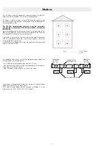
1. Frame
2. Electronic controller
3. 2-way modulating valve - Heating
4. 2-way modulating valve - DHW
5. 130 mm heat meter template
6. 1/4’’ F pressure port
7. Return temperature probe
8. Connection for M10x1 heat meter return probe
9. Primary drain cock
10. Differential pressure control valve
11. Mesh st 1/4’’ F pressure port
12. Heating flow temperature probe
13. Safety thermostat
14. Secondary drain cock + mesh strainer
15. Pump
16. Flow meter (t sensor)
17. Mesh strainer
18. Heating exchanger primary circuit drain
19. DHW temperature probe
20. DHW heat exchanger
21. Connection for M10x1 heat meter flow probe
22. Thermal safety solenoid valve (normally closed)
23. Thermal safety valve actuator
24. Water hammer arrestor
25. Heating exchanger primary circuit air vent
Characteristic components SATK2210. (LOW temperature)
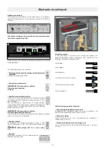
Hydraulic diagram SATK2210. and SATK2220.
TS
TA
2
2
V
V
V
V
V
V
3
4
7
12
13*
5
6
8
9
10
11
21
14
15
19
24
20
17
16
17
22*
23*
25
TA
2
V
V
V
V
V
V
3
4
7
5
6
8
9
10
11
21
13
14**
19
22
20
23
16
17
18
* SATK2210. only (LOW temperature)
12*
15*
* SATK2230. only
** SATK2240. only
3
9
4
7
10
8
5
2
1
21
11
15
20
19
18
12
17
6
16
14
24
25
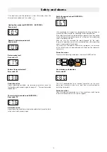
1. Frame
2. Electronic controller
3. 2-way modulating valve - Heating
4. 2-way modulating valve - DHW
5. 130 mm heat meter template
6. 1/4’’ F pressure port
7. Return temperature probe
8. Connection for M10x1 heat meter return probe
9. Primary drain cock
10. Differential pressure control valve
11. Mesh st 1/4’’ F pressure port
12. Heating flow temperature probe
14. Secondary drain cock + mesh strainer
15. Pump
16. Flow meter (t sensor)
17. Mesh strainer
18. Heating exchanger primary circuit drain
19. DHW temperature probe
20. DHW heat exchanger
21. Connection for M10x1 heat meter flow probe
24. Water hammer arrestor
25. Heating exchanger primary circuit air vent
Characteristic components SATK2220. (MEDIUM temperature)


