


12
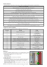
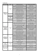
Heating function
Text (°C)
T
flo
w
(
°C
)
MIN
5
0
-5
-15
MAX
10
-10
20
15
25
30
-20
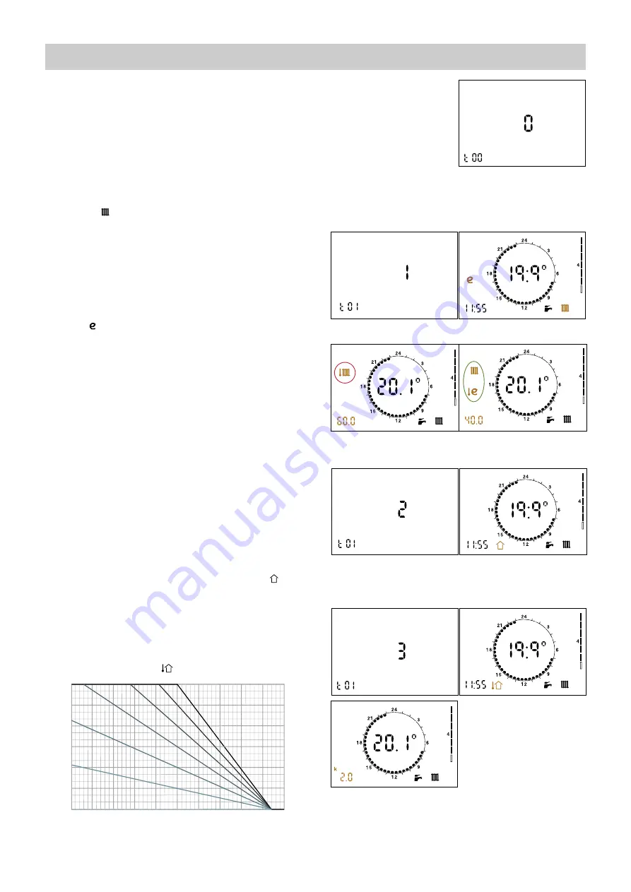
k = 3.0
k = 2.5
k = 2.0
k = 1.5
k = 1.0
k = 0.5
k = 0.0
MAX is the set temperature value
MIN is 45°C for HIGH temp. HIUs, 25°C for LOW temp. ones.
HIU setting at HIGH/LOW temperature
The HIU is set at LOW temperature by default (underfloor heating,
parameter t00 = 1). To change this setting and supply a system with
high temperature terminals go to the technical menu (see page 11)
and set parameter t00 to 0.
DEFAULT SETTING: set point regulation
(technical parameter t01 = 0)
When heating cycle activation is requested by the room thermostat,
the circulation pump is powered while the modulating valve is opened
gradually until the set point temperature is reached.
The circulation pump is stopped and the modulating valve is closed at
the end of the heating cycle. The heating cycle ON condition is indicated
by the blinking
symbol.
OPTIONAL SETTING: primary return temperature limit
(technical parameter t01 = 1)
When heating cycle activation is requested by the room thermostat,
the circulation pump is powered while the modulating valve is opened
gradually until the set point temperature is reached, if the return
temperature is lower than or equal to the set limit value. In case this
condition is not met, the flow temperature is reduced (by a maximum
of 15°C for HIU in HIGH temperature, and maximum 3°C if in LOW
temperature), in order to bring return temperature within the limit
values. When the flow temperature must be reduced in order to limit
return, the
icon appears on the display.
Heating flow/ primary return limit temperature setting
To set the flow temperature press the <SET> key until the symbol in
the red circle appears; for the return temperature limit press the key
until the symbols in the green circle are displayed. Use the <R> knob
to change the value (*).
The flow temperature range is:
25–45°C for heat interface units in LOW temperature
45–75°C for heat interface units in HIGH temperature
The primary return limit temperature range is:
15–42°C for heat interface units in LOW temperature
30–70°C for heat interface units in HIGH temperature
OPTIONAL SETTING: modulating temperature regulation with
compensated set point (technical parameter t01= 2)
When the function is enabled, the flow temperature is modified
(± 10°C with respect to the set point for HIU in HIGH temperature,
± 3°C if in LOW temperature) according to the temperature detected
by the return probe in order to maintain this latter temperature value
constant. This keeps the actual thermal output of the slab under
control, and consequently also the ambient thermal load. The thermal
response time of the system is thus minimised.
This feature should not be used in combination with thermostatic
radiator valves.
When the function is enabled the display shows the symbol
.
OPTIONAL SETTING: weather compensation (technical
parameter t01 = 3)
When the function is enabled, the flow temperature is calculated
based on the temperature detected by the outside probe (optional), in
accordance with the curve shown below. The “k” coefficient can be
changed by pressing <SET> button until the related setting appears.
The display shows the symbol
.
(*) if these set points cannot be changed you must set parameter t07
to value 0 in the technical menu (see “access to technical menu”
below). Parameter t07 = 1 “freezes” the operating set points to
prevent inadvertent modifications by the user.


